951
Model Code Page
61. Steering system
8. 11. 1990
6000--8750 611 3
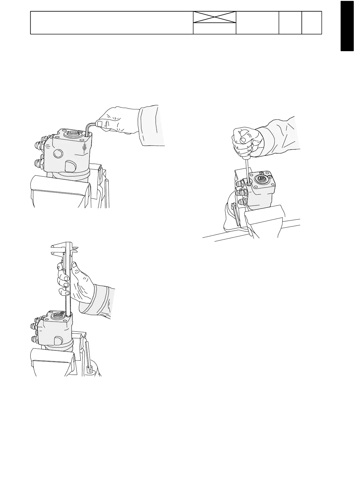
E. Cleaning shock valves and pressure---
limiting v alve
1. R emove the steering valve (see instr D). Secure the valve
in a vice with so ft jaws.
Note! There are two shock valves in the steering unit. Both
valves are similar.
2. Remove the plug on the shock valve (6 mm socket head)
and remove the sealing ring of the plug.
3. Measure and make a note of the dis tance between the ad-
justing screw and the upper face of the steering valve to facili-
ate the setting of the opening pressure of the shock valve.
4. Remove the adjusting screw (6 mm socket head). Shake
out a spring, washer and a ball.
5. Clean and check the parts and change faulty ones. Lubri-
cate all parts with oil before assembling. Minor damage to the
seat can be polished with a ball and fine grinding paste.
6. Fit the valve ball, washer and the spring.
7. Apply a little locking fluid to the threads on the adjusting
screw. Screw in the screw to the depth as measured in para-
graph 3.
8. Fit the sealing ring and thevalve plug and tightento a torque
of 40---60 Nm.
9. Unscrew the pressure---limiting valve plug (8 mm socket
head).
10. Remove the pressure---limiting valve insert by unscrewing
it with a 12 mm Allen key.
11. The pressure---limiting valve insert can be disassembled
by unscrewing the plug with a 4 mm Allen key. After that the
valve spring, seat and t he ball can be removed.
Note! When assembling the valve, screw the plug to the same
depth as it was before disassembling.
12. Clean all parts and the valve bore and lubricate the parts
with oil.
13. Make sure that there is a sealing ring o n the pressure---li-
miting valve insert. Fit the valve insert and tighten it to 40---60
Nm.
14.Fit the plug sealing ring and tightenthe plugto40---60 Nm.
15. Fit the steering valve (see instr. G) and check the steering
system pressures (see instr. A and B).