267
Model Code Page
31. Σ --- p o w e r s y s t e m
1. 8. 1998
8750 313 9
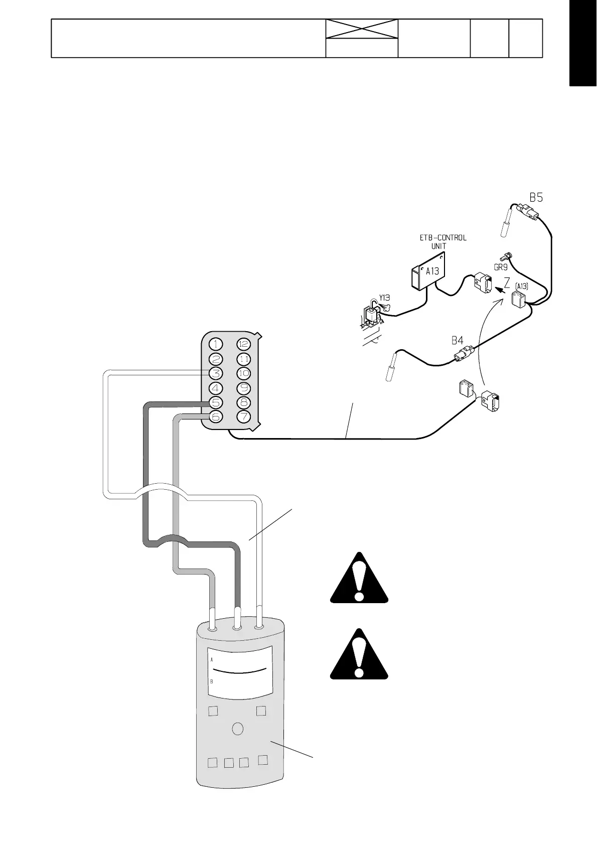
D. Checking and adjusting sensors with Fluke 123 ---oscillosc ope (if necessary)
1. Connect the measuring cable ETV 894310 (requires later connectors, G22507--- ) to the connector (A13) of the control unit.
Connect the oscilloscope (FLUKE 123 Scopemeter) to the measuring cable connector with cables ETV 894 400. A red wire to
connector pin 6 (foremost sensor channel A) and blue wire to connector pin 3 (rear sensor channel B). The middle wire
(black) of the oscilloscope is connected to connector pin 5 (earth) (see picture below).
ETV 894310
Measurements
G22507---
Blue
Black
Red
Red
Black
Blue
A
B
COM
6=A=Engine sensor
3=B=PTO sensor
Do not let wires touch
each others or tractor
frame, since the sen-
sororcontrolunitcan
be damaged.
ETV 894 400
Fluke 123
When connecting the
oscilloscope, the cur-
rent of the tractor
must be switched off.