101
Model Code Page
1. 10. 1999
8250--8750
321 9
32. ACB / ACD power lift
1. 9. 2002
H. Checking switch panel indicator lights
If the ACB/ACD functions properly, but the indicator lights
on the switch panel do not function correctly the following
steps must be taken:
--- detach the switch panel and move the connector on the
panel so that possible poor contacts are eliminated.
--- if an indicator light is still o ut of order the voltage
measurements shown in instruction F must be carried out.
---If the voltages are between allowable limits but the light is
still out of order the fault is in the bulb and the whole switch
panel has to be changed as a complete unit.
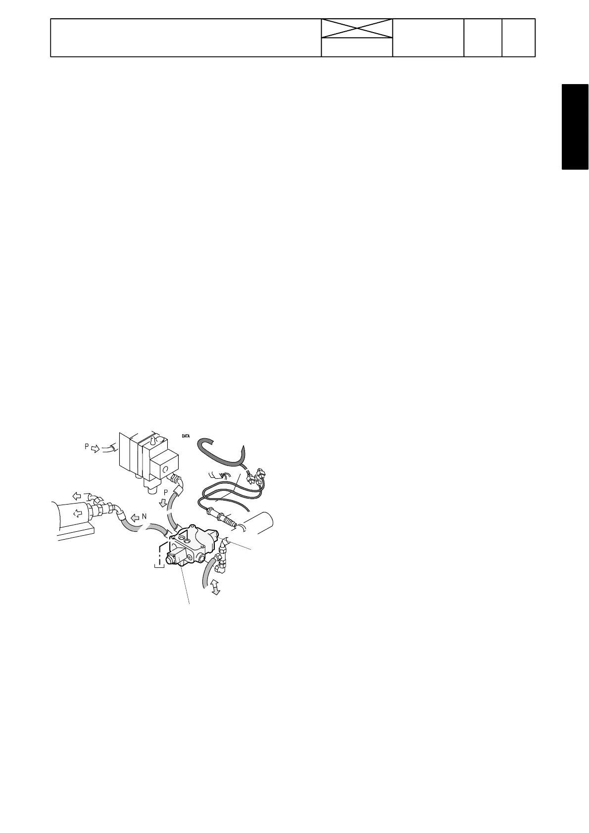
I. Checking control valve and i ts sole-
noid valves (not ACB)
If the lifting or loweri ng speeds do not function correctly, it is
necessary to clear up whether the fault lies in the electric
system or in the control valve (valve spools can get trapped
etc.).
Checking electric system:
Note! Diagnostic lights and fault codes, see instr. C.
Note! When chec king ACB power lift, there must be load in
the three---point linkage.
A
Y1E
Y2E
Connect an ampere--- meter in series with control valve sole-
noids. Y1E lowering (inner) and Y2E lifting (outer). Use ETV
894 220 when measuring these values, see page 101/1.
Lifting (with yellow push button) approx 1,60 A.........
(maximum current when the Autocontrol---rocker switch is
turned into the transport height).
Lowering (with yellow push button):
--- ACD approx 1,50 A..............................
--- ACB approx 1,40 A..............................
Lowering speed positions:
ACD ACB
1 approx 0,90 A approx 1,25 A.............
2 approx 1,00 A approx 1,50 A.............
3 approx 1,15 A approx 1,65 A.............
4 approx 1,30 A approx 1,85 A.............
5 approx 1,60 A approx 2,10 A.............
6 approx 1,85 A approx 2,35 A.............
7 approx 2,20 A approx 2,80 A *).............
8 approx 2,65 A approx 3,10 A *).............
9 approx 3,00 A approx 3,20 A *).............
*) Values inaccurate, since lowering speed is so large, that
ampere---meter reading is difficult to read off.
Resistance of solenoids approx 1,6 Ω..........
Checking the control valve:
If the measured values agree with the correct values above,
but malfunctions occur in t he lowering and lifting functions,
the contro l valve should be removed and checked (see
page 912/2).
Adjusting position sensor, ACB/
ACD
Normally the position sensor does not require any adjust-
ment. If the sensor has been removed, adjustment is
necessary.
1. Apply sealing compound to the sensor threads. Screw
the sensor locking nut to a point where the distance
between the nut front side and the end of the thread is
about 14 mm (rough adjustment)). Screw the sensor into
place until the lock nut touches the PTO housing.
Warning! If the sensor is screwed too deep, the eccentric
on the lifting arm shaft damages the sensor when the shaft
rotates.
2. Start the engine. Raise the lower links to the max. trans-
port position. By turning the sensor, find a point, where the
pump relief valve is blowing off *) and screw the sensor
from that point inwards 1/4 of a turn.
3. Lower the lower links.
4. Raise t he lower l inks again to the transpor t position and
ensure that the relief valve is not blowing off.
5. Raise the lower links to the max. upper position by using
the yellow push button. In this position the relief valve is
blowing off and the lifting cylinder stroke from the max.
transportheightis3 --- 4 m m .
6. After adjustment, tighten the sensor locking nut.
*
) When the pump is on, the load on the engine can be
heard easily.