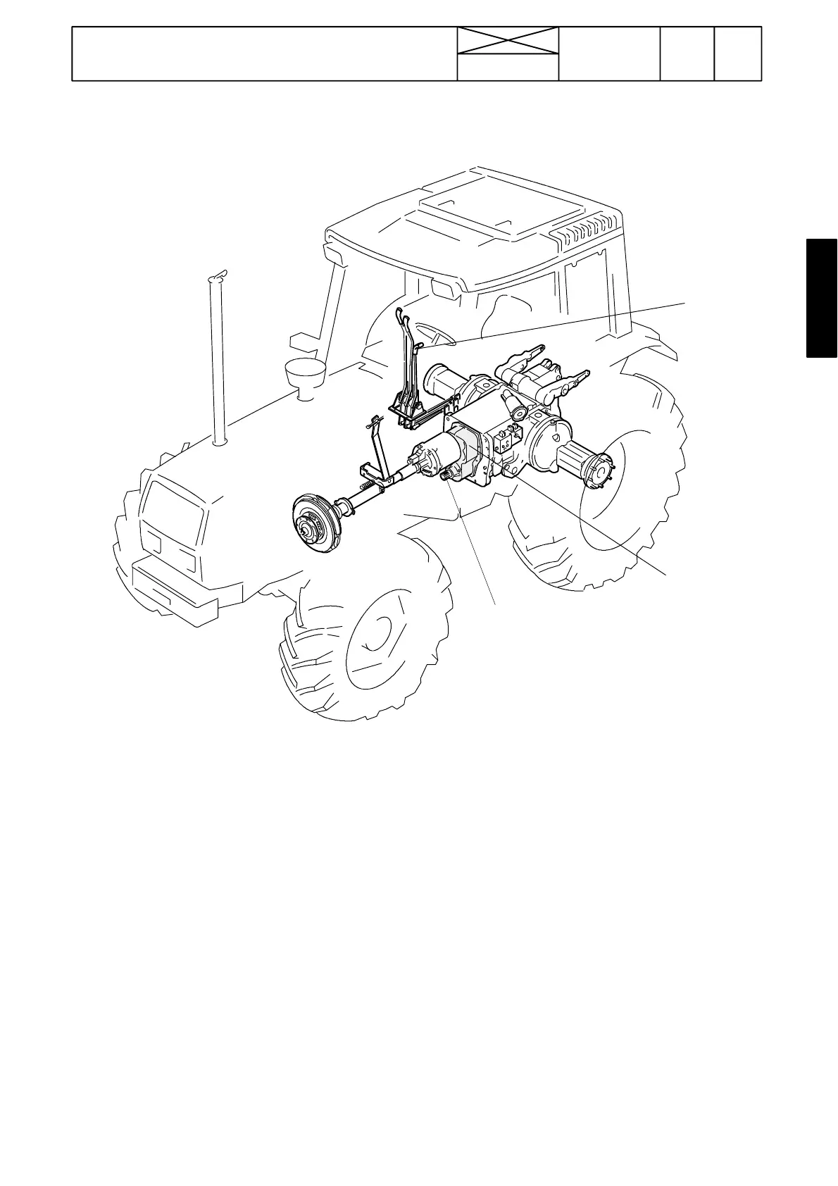
Figure 4. Power transmission
1. Reverse shuttle
2.Reverseshuttlelever
3. 4WD output shaft
747
Model Code Page
1. 11. 1998
6000--8750
17440
44. Quick---shift gear, reverse shuttle
and 4WD clutch
15. 5. 1993
Mechanical reverse shuttle, de-
scription
1
2
3
The reverse shuttle housing is attached to the gearbox front
end. The reverse shuttle is controlled mechanically with a
lever. In the reverse shuttle there is fitted a synchro mesh unit.
When changing driving direction, the tractor must be station-
ary and the clutch pedal must be pressed.
The selector fork rail rear end is led into the gearbox thr ough
the gearbox front wall. The reverse shuttle lever lower end has
been connected to the shifter lever, which turns the selector
lever and the selecto r fork on the synchromesh unit moves.
The reverse shuttle has pressure lubrication (see figures on
pages 440/10 and 440/16).
In the reverse shuttle housing lower part there is the 4WD
clutch and 4WD output shaft. On E---models, there are two
speed sensors on the reverse shuttle front end.
Important!
The picture above shows a transmission which has a 2---step
q u ic k --- sh if t g e a r. I f th e tra ctor h a s a 3 --- ste p q u ic k --- sh if t g e a r
(Delta Powershift), the reverse shuttle housing has a little dif-
ferent casting and additionally the i nput shaft length is differ-
ent (see picture on page 440/19). In addition, in the reverse
shuttle housing there is no impulse disc for E---models. The
4WD clutch and the 4WD output shaft have been reinforced
in connect io n with the Delta Powershift (see picture on page
440/21). Also the selector fork rail has been reinforced. Other-
wise the reverse shuttle is the same as earlier.