93
Model Code Page
31. Σ --- p o w e r s y s t e m
1. 10. 1999
8750, 8950 313 7
1. 9. 2002
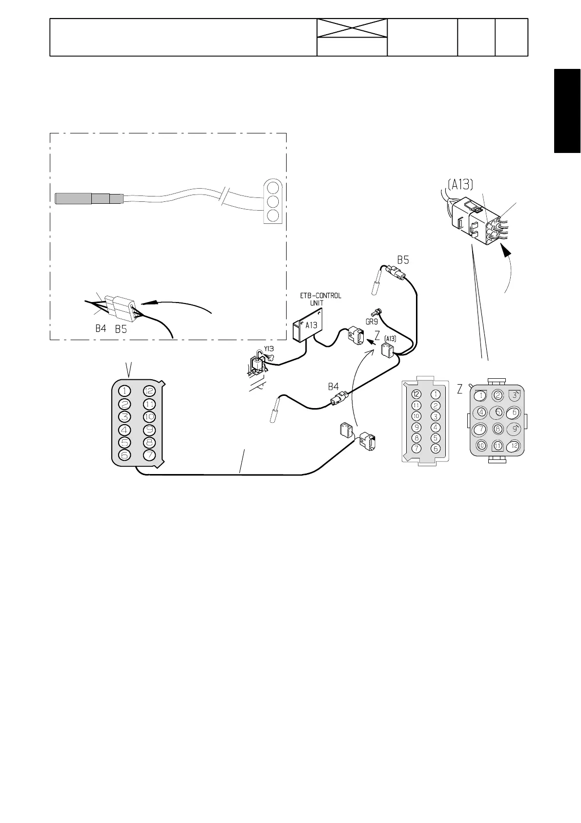
C. Fault tracing by measuring voltages
The lat est connect ors (G22507---) are tight, and connecto r rubber seals must not be opened, but the voltage measurements
are done by connecting ETV 894 310 into the wire loom. On the earlier connectors (---G22506) the measurements can be
done through the holes in connector A13 and/or through the holes in connectors B4 and B5. There are pin numbers o n the
connec tor hous ings.
Measure-
ments
---G22506
Measurements
G22507---
Measurements
---G22506
Earlier connectors (---G22506):sensorvoltagesare
measured from the connectors B4 and B5 through holes
on them while the current is switched on to the tractor:
Pins:
1<>2: supply 12---13 V (battery voltage). Earth.
2<>3: sensor signals
--- s i g n a l 0 , 7 --- 3 V a t t h e n o t c h , o t h e r w i s e 0 , 2 --- 2 V b e l o w
battery voltage.
1
2
3
1=+12 V (Brown)
2= Earth (Green)
3=Sign (White)
1
3
3
1
/
G22507---
---G22506
ETV 894310
+12
ETB
Sign PTO
GR9
Sign Eng
GR9
%display
PTO on/off
GR9
GR9
*)
*)
*)
*) Not in ver-
sions 2.0
If the Σ ---Power has malfunctions , disconnect connectors B4, B5 and A13 and reconnect them, so that possi ble poor con-
tacts disappear. If the malfunctions still exist, carry out t he following voltage measurements:
Earlier connectors ( ---G22506): Carry out measurements through the holes in the connectors.
The latest connectors (G22507---): Connect measuring cable ETV 894 310 between t he control unit connector A13 and
carry out measurements from the measuring cable connector.
Switch on current to the tractor and carry out the following measurements:
Pins
+<> --- measure battery voltage from the battery terminals (12---13 V)
1<>5 supply voltage (battery voltage) into the control unit, control unit earthing
1<>7 Versions 1.0 and 1.1: supply voltage (battery voltage) into the sensors, sensor earthing
1<>4 Versions 1.0 and 1.1: supply voltage (battery voltage) into the sensors, sensor earthing
6<>5 signal from foremost engine sensor B4
3<>5 signal from rearmost PTO sensor B5
Versions 1.0, 1.1 and 2.0: signal 0,7--- 3 V at the notch, otherwise 0,2--- 2 V below battery voltage
1<>12 Versions 1.0 and 1.1: supply voltage (battery voltage), display earthing
9<>12 Versions 1.0 and 1.1: control of PTO and %--- display
--- supply voltage, when the PTO is engaged, otherwise 0 V
9<>5 Versions 2.0: co n t r o l o f P T O a n d % --- d i s p l a y
--- supply voltage, when the PTO is engaged, otherwise 0 V
Start the engine:
Pins
11<>12 Versions 1.0 and 1.1: control of %---display
--- when the PTO is engaged: µ 9V=display0%,µ 1V=display99%.
11<>5 Versions 2.0: control of % ---display
--- when the PTO is engaged: µ 9V=display0%,µ 1V=display99%.
2<>12 Versions 1.0 and 1.1: Control of ETB---light
--- >10 V, when the higher output range is on (>25---30 % in display), otherwise 0 V.
2<>5 Versions 2.0: Control of ETB---light
--- >10 V, when the higher output range is on (>25---30 % in display), otherwise 0 V.