422
Model Code Sivu
35. Autocontrol IV
1. 1. 1995
6600E
8100E-- 8750E
351 4
1. 1. 1994
E. Potentiometer on the injection pump
The potentiometer must be adjusted so that when the accele-
lator pedal is in its extreme positions, the pedal movement is
not limited by the potentiometer because it does not resist that
kind of load.
Measure the potentiometer voltage between pins 2 and 3 in
connector B8C. The voltage reading must be below 3Vwhen
the accelerator pedal is the upper position and over 9 V when
the pedal is in the lowest position (difference between max.
and min reading at least 6 V). The voltage value should be
change without steps.
Resistance measurements of the potentiometer:
Black
Red
Yellow
1(+)
2 ( --- )
3(Sign.)
1 --- 2 :
about 1,01 kΩ
3 --- 2
--- spindle in, resistance about 0,62 kΩ
--- spindle out, resistance about 1,89 kΩ
Pins: Connector B8C
Socket X19/29
X5C/13
A2C/7
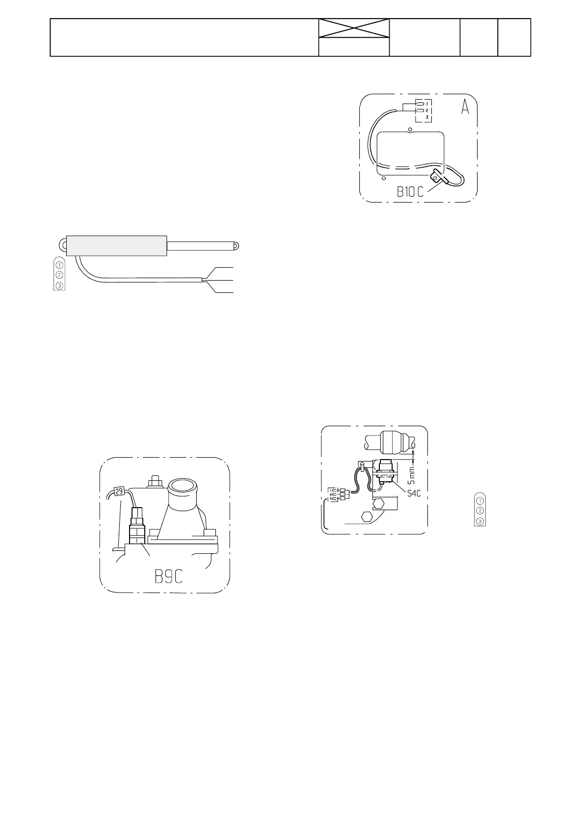
F. Sensor for engine coolant temperature
Press once the temperature key and the engine coolant tem-
perature can be seen in the display. Measure the coolant tem-
perature with a separate thermometer and compare the read-
ings. If the display reading is incorrect or there is no coolant
temperature reading, check the sensor and its wiring. Check
the connectors. Change if necessary the faulty sensor.
Resistance values of the sensor:
--- 2 0 ˚C 6480±1000 Ω
±0˚C 2450±320 Ω
+20˚C 1450±118 Ω
+40˚C 496±44 Ω
+60˚C 245±22 Ω
Pins: Connector B9C
Socket X19/27
Connector X5C/8
ECS connector A2C/30
G. Sensor for outdoor temperature
Press the temperature key twice and the display will show the
outdoor temperature. Compare the display reading with a
separate thermometer reading. If the display reading is incor-
rect or there is no outdoor temperature reading on AC IV dis-
play, check the sensor and its wiring. If these are OK the ECS
or the display unit can be faulty
Resistance values at certain temperatures:
±0˚C 10,00±1,00 kΩ
+22˚C 3100±50 Ω
Pins: Connectort B10C
Socket X19/26
Connector X5C/4
ECS connector A2C/29
H. Sensor for steering angle
1=black (sign)
2=blue (ground)
3=brown (+12 V)
Adjust the distance between the sensor and the front axle tie
rod joint to 5 mm .
Pins: Sensor connector S4C
Socket X19/25
Connector X5C/3
ECS connector A2C/15
Note! After fitting the sensor, check the function of the sensor
by following the signal lights on the lower face of the sensor.
When the wheels are straight ahead or turned less that ±15˚,
the green and yellow lights should light. When the wheels are
turned ±15˚or more the yellow light must go out and it must
not light between the steering angle ± 15˚and the max. steer-
ing lock. The function of the signal lights indicates that the
sensor supply is OK and that the sensor is functioning.