355
Model Code Page
34. Autocontrol ---III
6600E, 8100E 340 9
15. 6. 1992
1. 9. 1992
Harness looms and connectors
(see figure 3 on previous page)
1. Display unit (A3C). To the display unit rear side is connected
connector X11C.
2. Central processing unit (ECS) is fitted in the lever console
in the cab and is accessible after removing the lever console
side panel.
3. Slip Control selector (S5C).
4. PTO emergency stop socket (terminator).
5. Socket for connecting implement sensors to the AC ---III
system.
6. ECS harness loom.
7. Harness loom for cab.
8. Harness loom for engine.
9. Harness loom for rear sockets.
10. Harness loom for electro--- hydraulic power lift.
11. If you want to use the PTO unit manually , i.e. override the
ECS controls, connect connectors X9C.
Position of connectors
The following connectors are placed in the cab lever console
and are accessible after removing the console side panel:
--- A1C and A2C (central processing unit (2) connectors)
--- X1C (connector for wires from engine harness loom (8))
--- X2C (speed sensor wire connector)
--- X3C and X4C (connectors for rear sockets)
--- X 8 C ( o u t p u t s i g n a l s f r o m E C S )
--- X9C (PTO manual control connector)
Connector X5C (switches from gear lever knobs) is on the RH
side mudguard in the front part of the lever console
Electro---hydraulic power lift connectors which are in the lever
console,areaccessibleafterremovingtheECSbox(2).
Connector B8C (fuel injection pump potentiometer) is placed
under the instrument panel
Connector X19 (sensors in front part of the tractor) is placed
on the cab front wall on the RH side.
Figure 4. Central processing unit (ECS) is placed in the lever
console i n the cab. Central unit is a ccessible when the console
side panel is removed.
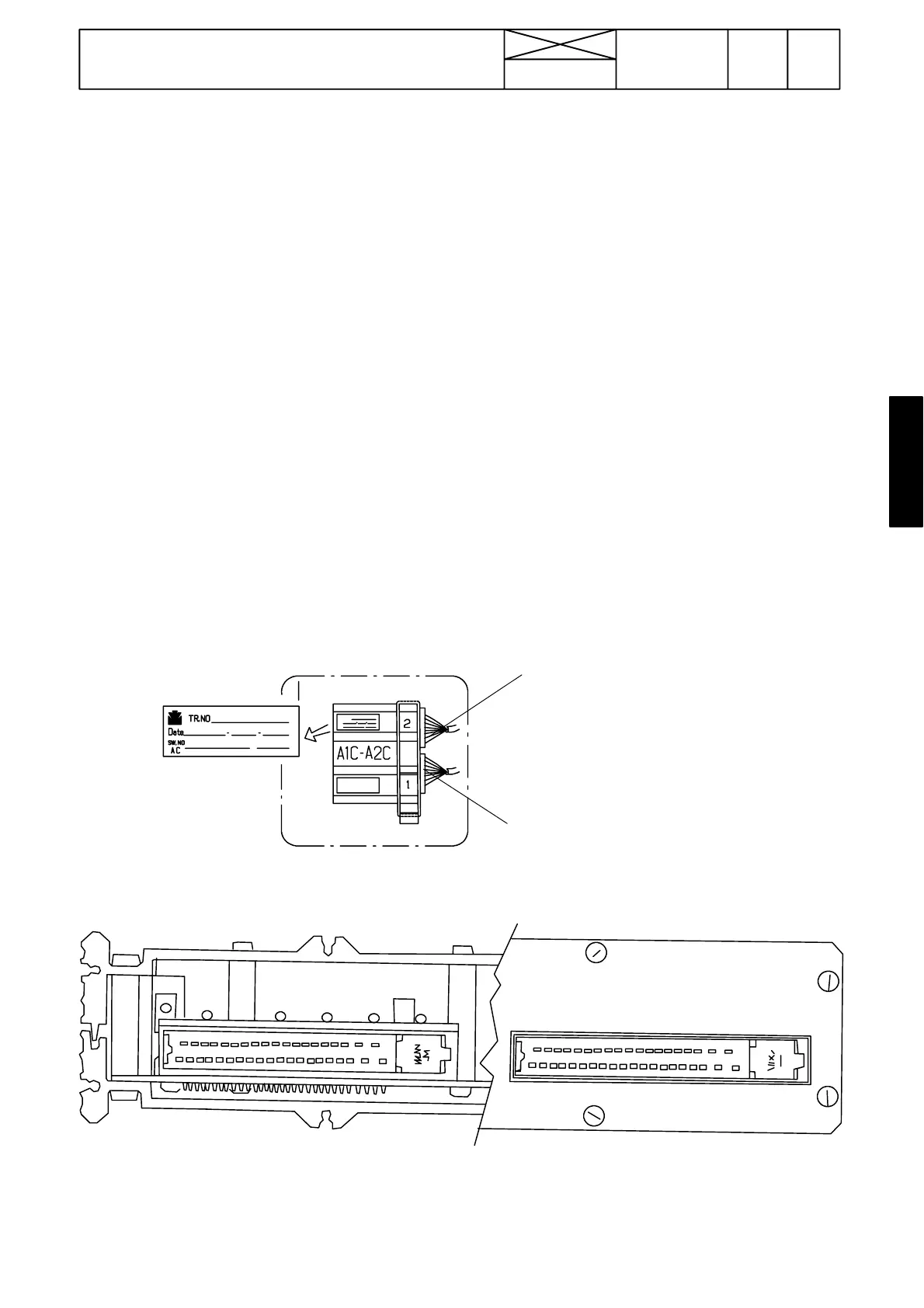
Figure 5. Rear side of the ECS
V oltage measurements can be done from the pins of connectors A1C and A2C. The pins have been numbered. When
measuring output signals the pins must have a load.
Supply voltage can be measured from connector A2C (earth A2C:1. Supply voltage A2C:2, A2C:21 and A2C:25 (current
must be switched on).
Upper connector A2C
Lower connector A1C