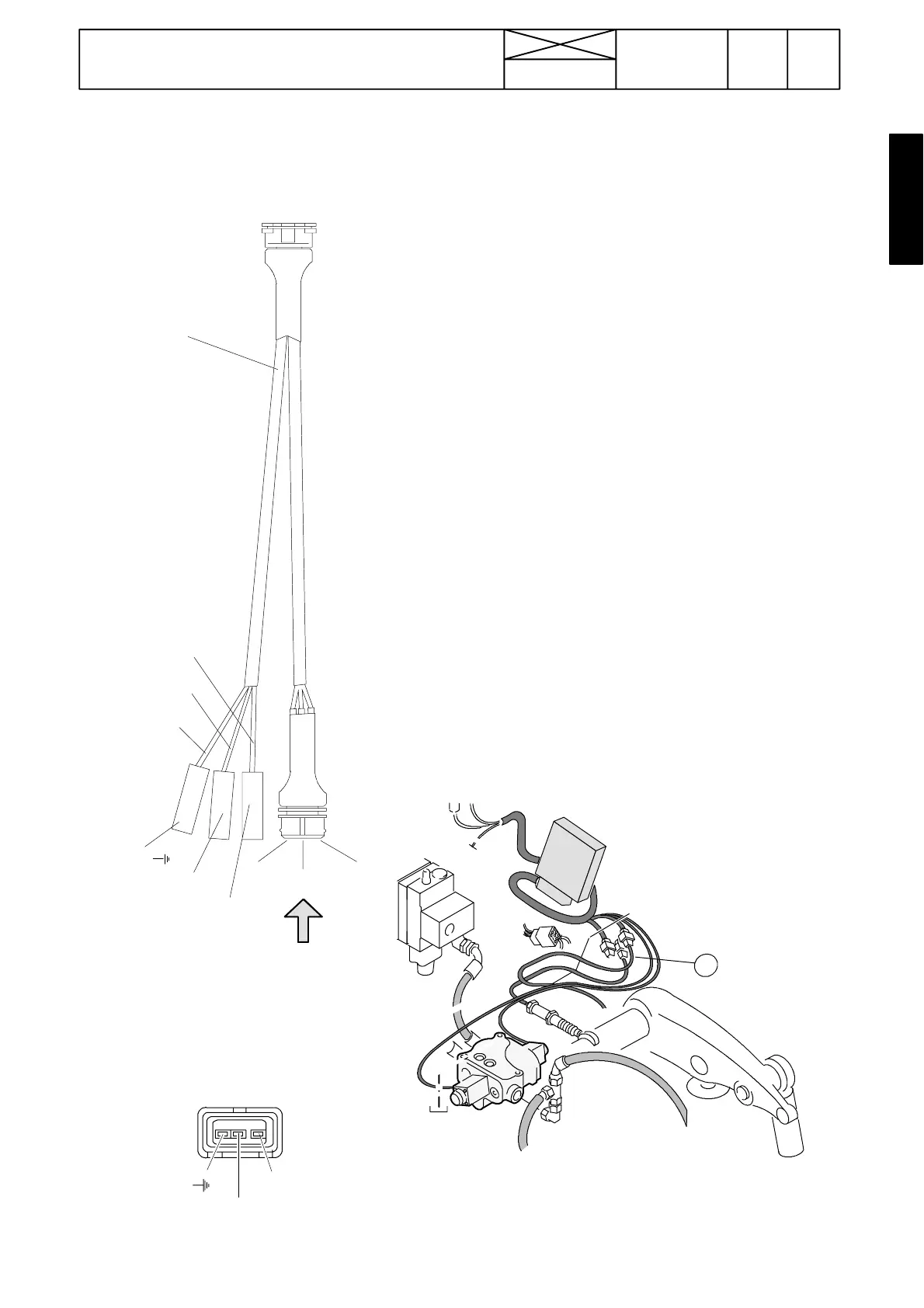
2. Measuring i nternal voltages of position sensor and draft sensors
Figure 1. Tool for measuring the sensor voltages
Red = supply voltage=3
Blue = signal volt age=2
Black = earth lead=1
Red (3)
Blue (2)
Black (1)
The condition of the sensors can be checked by measuring
the sensor supply and signal voltages with the aid of a spe-
cial tool.
Connect the tool into the power lift by opening the position
sensor or one of the two draft sensors connectors and by
fitting the tool between the lead. Switch on current and acti-
cate the power lift with lift/lower switch.
The correct values should be:
Position sensor: (ACB / ACD)
--- Measure the sensor supply voltage in the alternating
current (AC) position of the multimeter. The value should be
between the red and black connectors: 6,3---7,7 VAC
--- Measure the sensor signal voltage in the alternating
current (AC) position of the multimeter. The value should be
between the blue and black connecto rs:
1,2...2,5 VAC lower links down.
3,0...5,0 VAC lower links up.
Draft sensors:(AC,ACB,ACD)
--- Measure the sensor supply voltage in the direct current
(DC) position of the multimeter. The value should be bet-
ween the red and black connectors: 9,5 --- 10,5 VDC
--- Measure the sensor signal voltage in the direct current
(DC) position of the multimeter. The value should be bet-
ween the blue and black connectors:
2,5 VDC max pull.
7,5 VDC max push.
5,0 VDC when lower links are unloaded..
Note! If the sensors do no t receive the supply voltage,
check the power lift fuses and the lead connectors. If these
areOKthepossiblefaultmaybeinsidetheAutocontrol
electronic unit which should be replaced.
View A
Sensor connectors (A) are placed in the lever console in the
cabandareaccessibleafterremovingconsolesidepanel.
Order no
ETV 894 100
Blue
Yellow ---green
Brown
95
Model Code Page
32. Electro---hydraulic power lift
6000--8400 320 13
15. 5. 1996
1. 9. 2002
1
2
3
A
1
2
3
A