773
Model Code Page
442. Reverse shuttle
6000--8750 442 3
1. 1. 1995
15. 5. 1993
C. Fitting the reverse shuttle
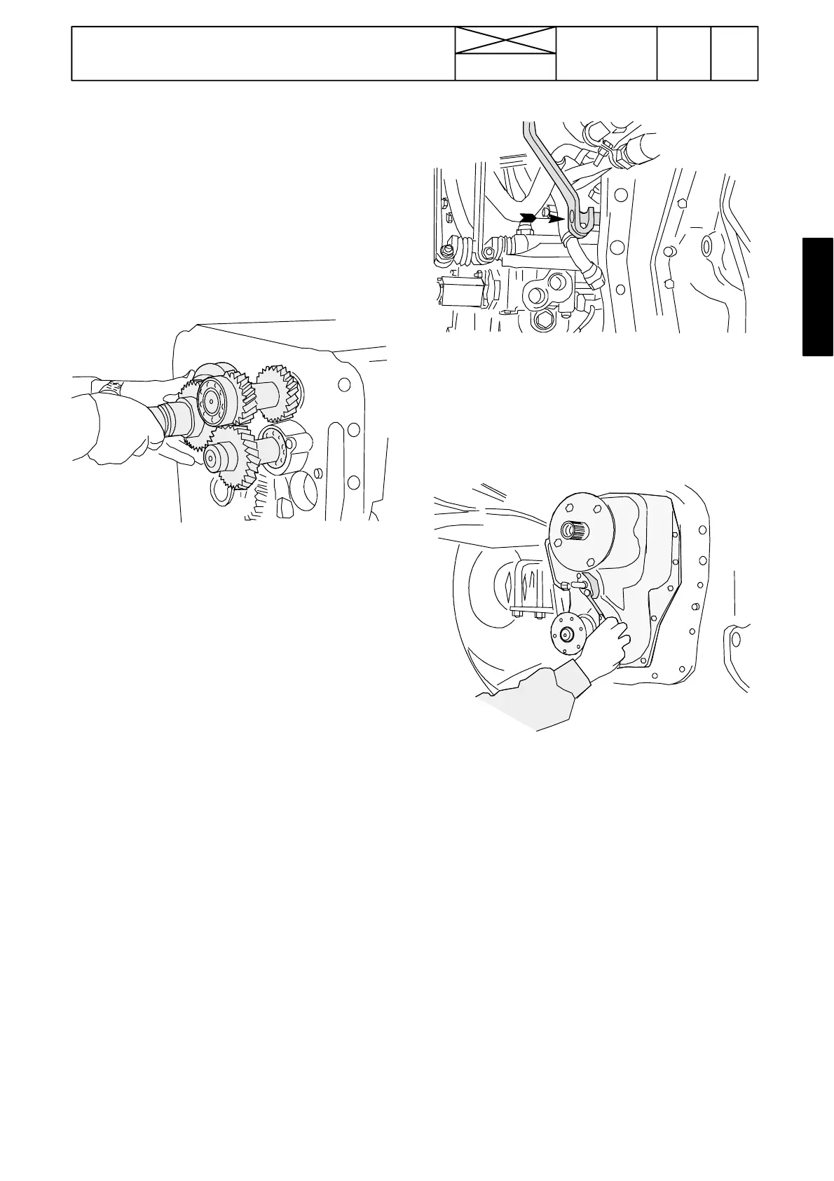
1. Fasten the thrust bearing with universal grease to its place
on the gearbox input shaft front bearing cover. In connection
with the 2---step quick---shift gear, fasten the impulse disc (on
E---models only) and its support tube into the reverse shuttle
housing (o---ring fix the impulse disc but universal grease can
be used if necessary).
Note! Before fitting the reverse shuttle, ensure that the gear-
box layshaft front end cover has been fitted in the correct way
(otherwise it prevents the reverse shuttle layshaft from enter-
ing fully home).
2. Fit the reverseshuttle shafts and the synchromesh unit onto
thegearboxfrontside(seefigureabove).
3. Place the selector fork together with sliding pieces (sliding
pieces can be fixed with universal grease on the fork during
mounting) onto thesliding couplerand guide the select or fork
rail through the hole on the gearbox front face. Fasten the fork
to the rail with a locking pin. With effect from tractor ser. no.
661937 the selector fork and the sliding pieces have been
modified. Fit the latest parts onto the reverse shuttle despite
the condition of the earlier part. See also page 421/ 2.
Note! Fit the reverse shuttle input shaft roller bearing into its
location on the housing. The foremost ball bearing is fitted
after the housing is in place against the gearbox front side.
4. Make sure that the 4WD output shaft nut has been fully tigh-
tened and then unscrewed one turn (2---step quick---shift
gear) or one and a half turn (Delta Po wershift) . Check that
the lugs on the 4WD multi---disc clutch pack are accurately in
line with each other.
5. Apply sealing compound to the contact surface between
the gearbox and the reverse shuttle housing.
6. Push the housing into place and turn the 4WD clutch so that
the lugs on the discs engage with the grooves on the clutch
drum.
6. Push the housing against the gearbox front side and screw
four guide pins (M8, l= 100 mm) into the holes for housing
bolts.
7. Push the housing fully home (tap carefully with a copper
bar, but do not use too much force). Remove the guide pins
and tighten the reverse shuttle fixing bolts to 23 Nm.
Note! Ensure that the impulse disc is correctly in place
(E---models).
8. Fit the selecto r fork rail locking ball, spring and the plug.
Push the selector lever inwards and check that it has engaged
with the groove on the rail rear end.
9. Fit the input shaft ball bearing and its circlip. Fit the smaller
circlip onto the shaft.
10. Tr a c t o r s w i t h 2 --- s t e p q u i c k --- s h i f t g e a r o r w i t h o u t
quick---shift gear: Screw the long bolt into place under the
lubricating oil distributor piece and fit the distributor piece.
11. Connect the external pipes.
12. Attach the quick---shift gear to the reverse shuttle: 2---step
quick---shift gear, see instr. 4412A. 3 --- s te p qu ic k --- sh if t g ea r,
see instr. 444 1A points 19---26.
13.Assemblethetractorframe(seeinstr.4412Bor 423 5A).
Note! On AC IV models, fit the gearbox speed sensor B2C
onto the RH side of the shuttle housing, see page 351/3.