335
Modell Code Page
33. Agrodata---instrument
1. 8. 2000
6000--8950 331 5
15. 4. 1995
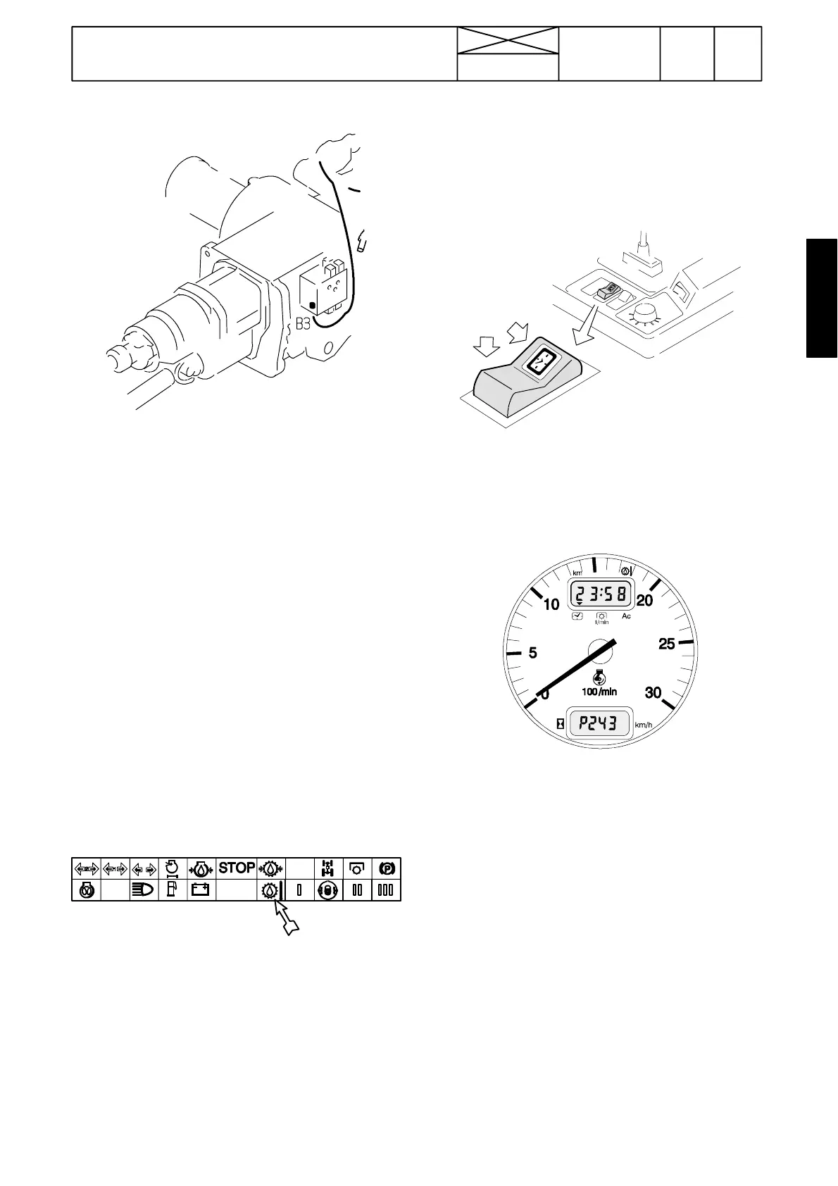
C. Gearbox temperature sensor B3
Note! The gearbox oil temperature must be higher than
+40˚C, before the display shows the temperature. At the
lower temperatures the display shows LO.
If the Agrodata ---unit does not show the gearbox temperature,
check the sensor and its wiring.
Pins:
Sensor pin
X34 pin 9 (in the rear part of the lever console) (---J05132)
X25 pin 9 (under the instrument panel) (---J05132)
X26 pin 26 (white connector behind the Agrodata---instr.)
X13 pin 20 (on fastening plate in lever console) (J05133---)
If you doubt that the sensor wiring is faulty, switch on the igni-
tion. Select the gearbox temperaure into the Agrodata display
(follow the black arrow).
Detach the wire from the sensor (under the servo valve block)
and connect it to the tractor frame. When the wire is earthed,
some temperature values must flash in the display and three
lines must be visible in the display, if the display and the wiring
is OK.
Some sensor resistances:
--- 75 ---90 Ω (~ +90˚ C)
--- 200 ---250 Ω (~ +60˚ C)
(resistance value increases when temperature lowers).
Note! There is an other temperature sensor on the front face
of the servo valve block, which lights up the warning light, if
the gearbox oil temperature rises too much. Also the Stop---
light starts to flash.
2. Calibrating the instrument for dif-
ferent tyres
1. Remove the switch C by prying it carefully. Do not discon-
nect the wires.
2. Switch on current with the ignition switch.
C
3. Connect the switch pins 1 and 7 with an auxiliary wire and
press at the same time the switch front edge for over 3
seconds. ”P” appears in the lower display and the valid code
number (e.g. P243). The first digit is flashing. Remove the
wire.
4. Adjust the hundreds by pressing the switch rear edge.
5. When the hundreds are correctly adjusted, press the switch
front edge and tens start to flash.
6. Adjust the tens by pressing the rear edge and then press
the front edge, at which time single units start to flash.
7. Adjust the ones by pressing the rear edge.
8. Finally press the front edge for over 2 seconds. Calibrating
has been carried out and running hours appear in the lower
display(readthenotebelow).Fittheswitch.
Note! In the beginning of the production (the first 20 tractors),
the switch pins 1 and 7 must be once again connected with
auxiliary wire and after that the switch front edge is pressed
over 2 seconds.
Note! The code number value can vary between
P100---P299. When pressing the switch rear edge, the code
value changes from a smaller value to greater one. The code
numbers and corresponding tyres are listed in the table on the
next page.