268
Model Code Page
31. Σ --- p o w e r s y s t e m
1. 10. 1999
8750 313 10
1. 8. 1998
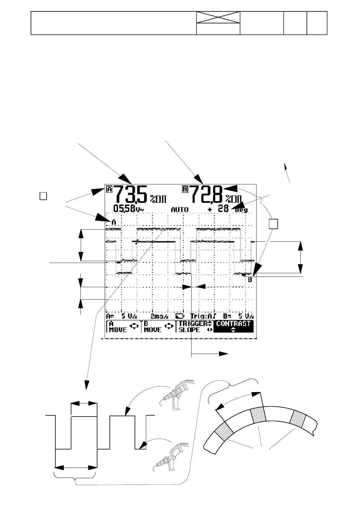
INTERPRET ATION OF OSCILL OSCOPE WAVES AND SPECIFIED VALUES
PULSE RATIO A
60---75 %
(Change max. 5 %.
750---2200 r/min)
PULSE RATIO B
PTO 1000/540E: 40---55 %
PTO 1000: 60---75 %
(Change max. 5 %.
750---2200 r/min)
PHASE DIFFERENCE
Value acc. to tractor.
Change max.10˚
(750---2200 r/min)
B PTO SENSOR
A
ENGINE
SENSOR
min. 10 V
5V
(A) 0 V
min. 10 V
(B) 0 V
B---wave moves to the right,
when the shaft is loaded with
hydraulic valves or with PTO.
73,5 %
100 %
Battery
voltage
minus
0 , 2 --- 2 V
0 , 7 --- 3 V
+28˚ PHASE
The phase difference indicates the time difference of
the waves in channels A and B as degrees within
---160˚...0˚...+200˚ (the total wave length is 360˚ ).
The reading does not mean the angle of the crank-
shaft, since the sensor sends 10 pulses per one engine
rotation. The sign (+/ ---) changes at degree values of
0˚ and +200˚ ( = --- 1 6 0 ˚), since at these degrees the
Oscilloscope changes the comparing to the previous/
next wave.
The greatness of the phase difference value is not
important, only the change of this value is important.
The position of the transmission mechanical parts (can
be changed during reparations) and the PTO loading
affect the phase difference. The sensor adjustment
and the PTO unit type in the B channel affect the wave
width (impulse surfaces can have different lengths).
2. Select oscilloscope settings; channel A DUTY (pulse
ratio %) and channel B PHASE (phase difference B>A
(deg)) and DUTY (pulse ratio %). Display range of both
channels; 5 V/d, 2 ms. More detailed instructions for the
use of the oscilloscope can be found in the end of this
instruction on pages 313/12---13.
Notch
100 %