Floor hatch
651
Model Code Page
41. Clutch
1. 1. 1995
6000--8750 411 3
15. 5. 1993
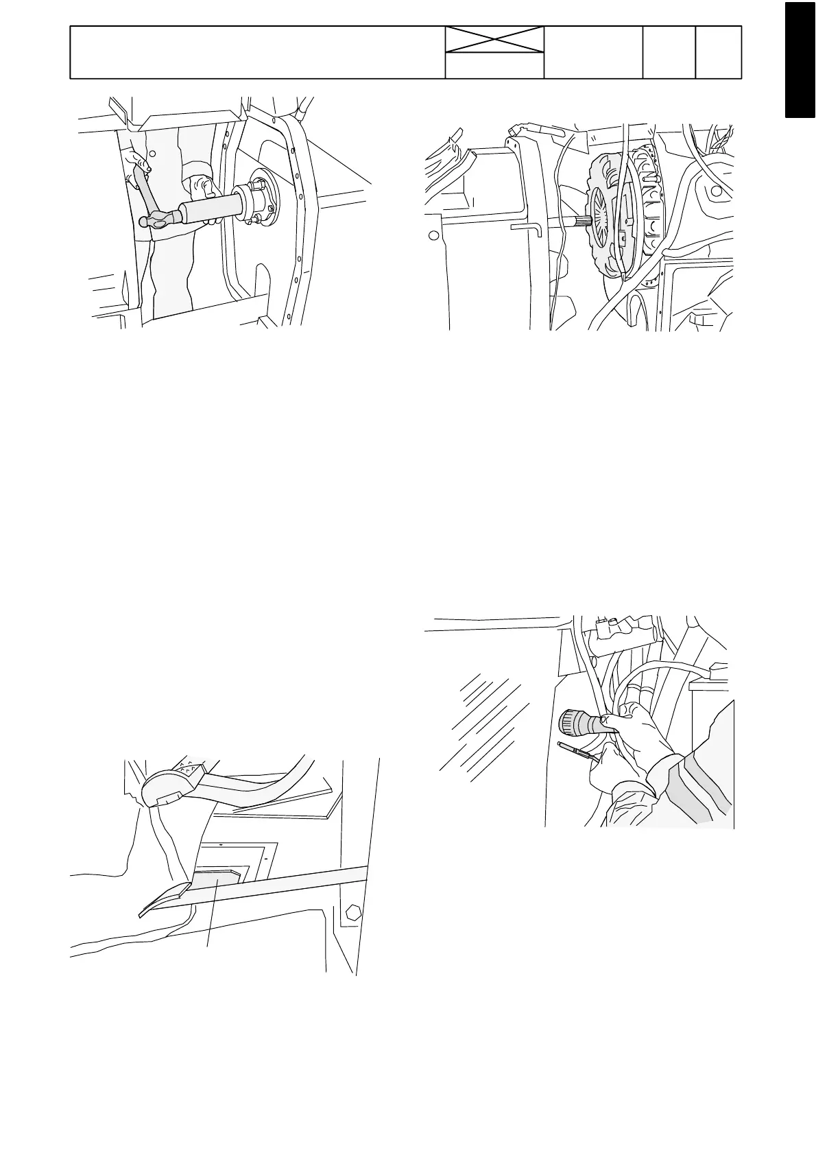
3. Knock in the tube with ETV 892 380 and remove the bear-
ing. Fit a new bearing with ETV 891 900
Note! Check that the bearing comes up against the spacer
ring.
Note! Check also the sliding ring inside thetube guide sleeve.
4. Assemble the tractor frame at the clutch (see instr. D).
D. Asse mb ling tractor at clutch
1. Push the pump drive shaft backwards fully home. Push the
clutch shaft backwards until it engages into the coupling
sleeve. Important! The pump drive shaft should be fitted in
the correct way. The end which has a marking groove (and
letter E) should be turned to the engine side.
Important! Guide the rear end of the propeller shaft onto the
4WD output shaft front end splines (659478---).
Note! If necessary, guide the coupling sleeve through the
floor hatch. Grease splines with pressure---resistant grease.
1. Push the units together so that theshafts engage.If necess-
ary, rotate the flywheel so that the splines engage.
2. Tighten the bolts to correct torque.
3. Connect the oil cooler hoses on the left hand side. Connect
the fuel hoses and the fuel gauge wires (on the right hand
side).
4. Connect the cab earth l ead to the cab front wall. Connect
the hoses to the steering valve according to the marks. Con-
nect the starter motor cable.
Important! With effect from tractor ser. no. 659478, connect
the release cable front end to the lever upper end, work
through the access hole on the frame.
5. Fit the throttle cable and the socket to the front wall on the
right hand side.
6. Connect the windscreen washer hoseand cable connecto r.
Connect the heater hoses.
7. Connect the stop control to the injection pump.
8. Adjust the clutch (see instr 2A). Remove all supports. Fit
theenginehoodplates.
9. Connect the propeller shaft front flange joint. Fit the guard
under the tractor.
Note! Fit the floor hatch if opened.