297
Model Code Page
32. Electro---hydraulic power lift
8. 11. 1990
6000--8400 320 11
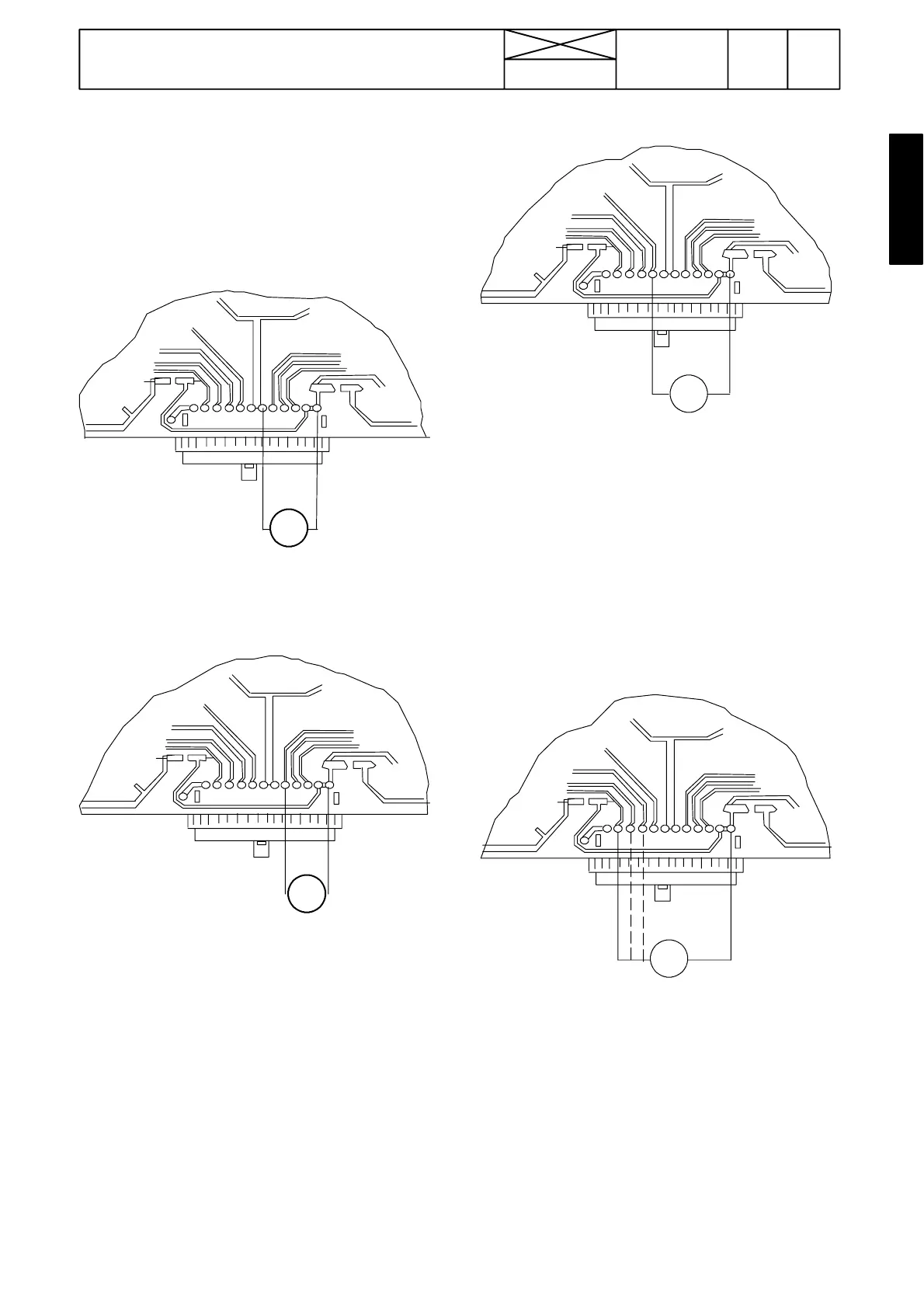
B. Voltage measurements
Turn the current on with the ignition switch and activate the
control system with the lift/lower switch (do not detach the
connector from the switch panel). Carry out measurements
on the rear side terminals according to the figures a---d below.
Checking supply voltage
V
16
12
7
---
+
Figure a) Measuring supply voltage: measure voltage be-
tween terminals 1 and 6
Correct value is 9,5--- 10,5 V
V
1
12 5
---+
Checking lowering speed selector
Figure b) Checking lowering speed selector: Measure volt-
age between terminals 1 (or any frame contact) and terminal
5 with every selector (S7E) positions:
Position Terminal 5
1 0 , 9 --- 1 , 1 V
2 1 , 7 --- 1 , 9 V
3 2 , 4 --- 2 , 8 V
4 4 , 3 --- 4 , 9 V
5 6 , 0 --- 6 , 8 V
6 9 , 5 --- 1 0 , 5 V
Checking transport height selector
V
1
12
8
---
+
Figure c) Checking transport height selector: Measure volt-
age between terminals 1 (or any frame contact) and terminal
8 with every selector (S8E) positions.
Position Terminal 8
4 9 , 5 --- 1 0 , 5 V
5 7 , 6 --- 8 , 4 V
6 5,7---6,3V
7 3 , 8 --- 4 , 2 V
8 1,9---2,1V
90
Checking draft control selector
V
1
1011 9
---+
Figure d) Checking draft control selector: Measure voltage
between terminals 1 (or any frame contact) and terminals 9,
10 and 11 separately with every selector (S9E) positions:
Pos. Terminal 10 Terminal 9 Terminal 11
P 9,5---10,5 V 0---0,2 9,5---10,5 V
1 3 , 7 --- 4 , 1 V 0 --- 0 , 2 7 , 7 --- 8 , 5 V
2 1 , 8 --- 2 , 0 V 0 --- 0 , 2 7 , 7 --- 8 , 5 V
3 1 , 8 --- 2 , 0 V 0 --- 0 , 2 9 , 5 --- 1 0 , 5 V
4 0 1,7---1,9 V 7,7---8,5 V
5 0 1,7---1,9 V 9,5---10,5 V
Note! If the supply voltage deviates from the correct value, the
fault lies in various connectors. If other values are incorrect,
the fault lies in the switch panel, which should be changed.