PTO 1000/750 (540E)
D
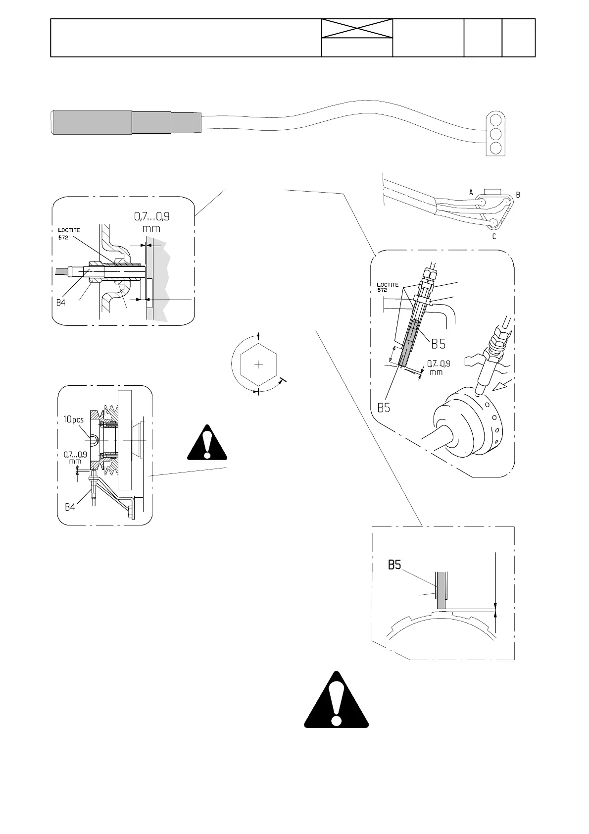
0,7---0,9 mm
Loctite 572
The distance between the sensor end
and the impulse surface must be at
least 0,7 mm (at least 1/2 turn), other-
wise the sensor can be damaged
mechanically.
258
Model Code Page
31. Σ --- p o w e r s y s t e m
1. 10. 1999
8750, 8950 313 4
1. 6. 1999
D. Sensors B4 and B5, versions 1.0, 1.1 and 2.0
1
2
3
1=+12 V (Brown)=A
2= Earth (Green)=B
3=Sign (White)=C
1
2
25
---G22506
G22507---
B
A
C
1
2
3---7 mm
A, C and D
In connection with sensor
replacement, screw a new
sensor into the sleeve to the
same depth as was the
earlier sensor. Use Loctite
572 when fitting the sensor.
Turnthesleeve2,untilthe
sensor touches the measur-
ing wheel (not at the notch)
andthenopenthesleeve
1/2---2/3 of a turn.Lockthe
sensor with nut 1 (sleeve
thread M18x1,5).
B
Screw the sensor first fully home until
the sensor end touches the measuring
wheel (not at the notch) and open it
then 3/4 turn. Lock the sensor with a
locking nut (sensor thread is M12X1).
H02431---
---H02430
PTO 1000
Stoptheenginebefore
sensor adjustment.
min.
max.
distance
0,7 mm
distance
1,0 mm
8750
8750
Version 1.0
Versions 1.1 an 2.0
Note! On 8950Hi models the foremost sensor is placed
in front of the DPS and the sensor is adjusted so that the
distance between the sensor end and the impulse sleeve is
0,7 ---0.9 mm (not at a notch).
Note! Versions 1.0 and 1.1: The ETB---light indicates by
flashing, if the sensor signals are not OK (e.g. there is no
signal from one sensor), ETB---light is flashing in time 0,5
sec on and 0,5 sec off. This flashing indicates, that the sen-
sor is faulty or there are poor contacts in the connectors/
wires. Also wrong adjustment can cause malfunctions.
IMPORTANT! Versions 2.0 and 3.0: Iftheenginespeed
sensor is damaged, the ETB---light flashes in above men-
tioned time twice, after which there is a pause of 1,5 sec. If
the PTO sensor is faulty, the ETB---light flashes three times,
after which there is a pause of 1,5 sec.