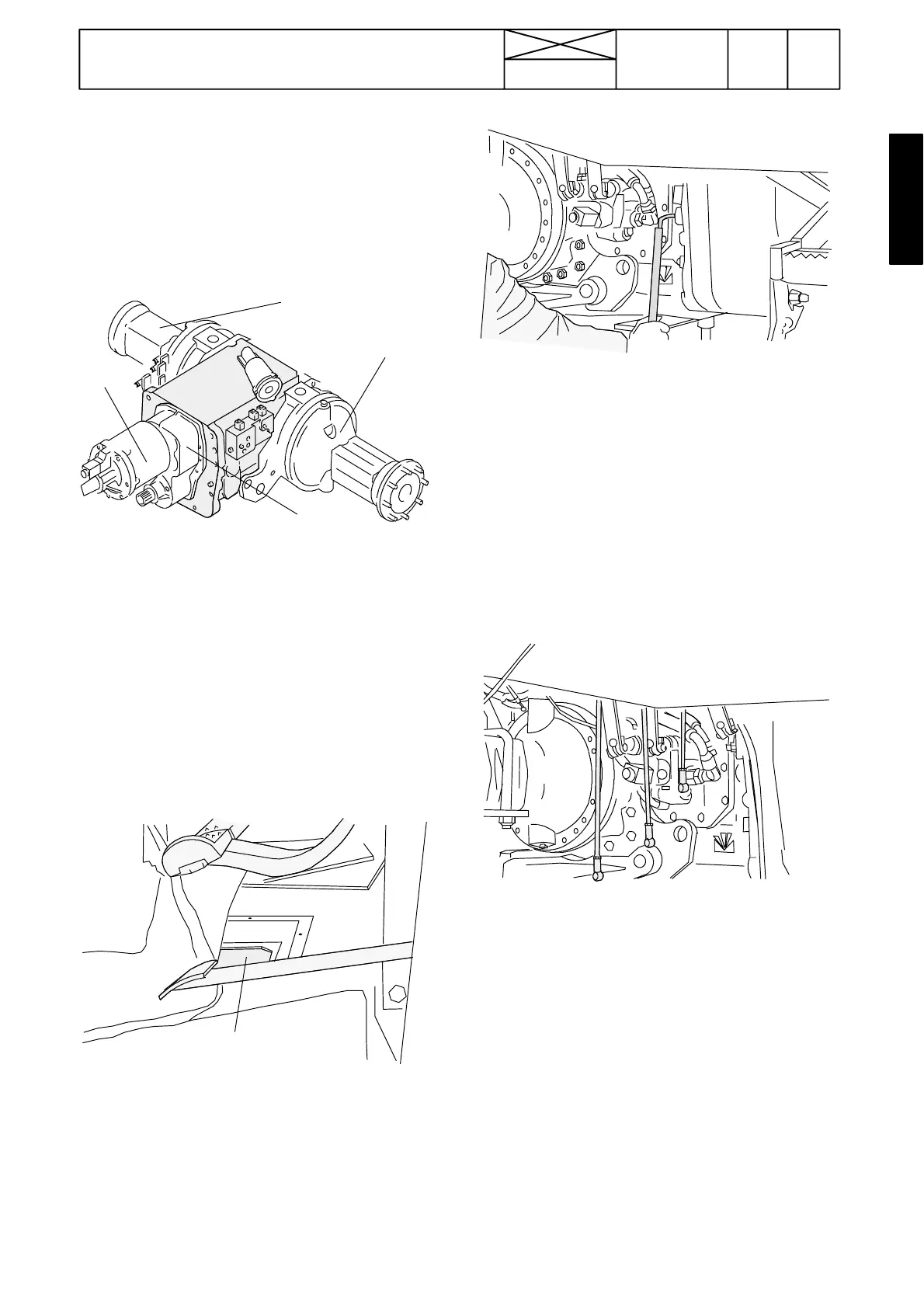
Floor hatch
721
Model Code Page
42. Gearbox
1. 1. 1995
6000--8750 423 17
8. 11. 1990
5. Fitting gearbox
Note! If You have removed the cab, attach all transmission
components and hoses to the tractor frame and after this fit
the cab (fitting the cab, see section 80). In instruction below
the cab, however, is in place.
A. Fitting g earbox
1
1
2
3
Note! Assemble the transmission unit as shown in the above
figure. Attach every part, hoses and pipes, which were remo-
ved after splitting (see Op. 1A). Fit the rear wheels and sup-
port the transmission unit with trestles equipped with castors.
Note! Push the pump drive shaft into the gearbox i nput shaft
and place the connecting sleeve onto the quick---shift gear/
DPS input shaft splines (or reverse shuttle splines).
Important! The pump drive shaft should be fitted in the cor-
rect way. The end with a marking groove (and letter E) should
be turned to the engine side)
1. Push at the rear wheels and connect the gearbox to the fuel
tank so that the guide pins and studs engage with their holes.
Note! Guide the connecting sleeve onto the clutch shaft thro-
ugh the floor hatch. Rotate the flywheel through the hole on
the flywheel hous ing so that the pump drive shaft splines
engage. Guide the propeller shaft rear end splines onto the
gearbox 4WD output shaft on the tractors which have the
Delta Powershift.
2. Tighten the bolted frame joint to the correct torque.
3. Remove the RH side rear wheel. Fasten the auxiliary
hydraulic valve bracket onto the gearbox (work through the
hole on the mudguard). Connect oil hoses to the end plate of
the valve chest.
4. Connect the cables to the shifter levers and to the lower
ends of the gear levers.
5. Connect the hoses of the hydraulic power lift control valve.
6. Connect the hoses to the pressure filter and attach the filter
housing.
7. Connectthe shifter rods to the lower ends of the gear levers.
Connect electric wires to the control valve so lenoids.
8. Connect the reverse shuttle lever lower end to the shifter
lever.