474
Model Code Page
37. Autocontrol 5 / 5.2
1. 8. 2000
370 16
6250--8950
1. 10. 1999
D. Checking pressures in shuttle
clutches in AC 5 and 5.2
See also the setting orders in instr. 370---24D.
Note! If the shuttle has malfunctions or if the shuttle has
been repaired or the proportional valves have been
changed, the function of the control system must be
checked. These tests ensure, that the pressure in the tractor
low pressure circuit is high enough and that the F/R propor-
tional valves are functioning.
Note! Ensure that the transmission oil temperature is
between +30˚C...+60˚C before work.
31965400
33743900
1. Measure pressure in the tractor low pressure circuit ac-
cording to instr. 911.
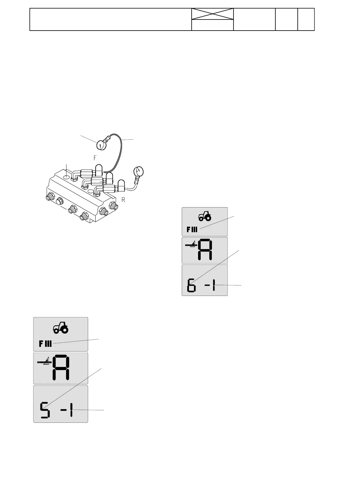
2. Connect a pressure gauge of 25 bar onto the F --- d i r e c -
tion pressure---test point (second point from the right, see
also picture on page 440/25).
3. Activate the setting mode according to instr. A on page
370/14.
4. Step with the DPS push buttons (in the speed gear lever
knob) and select point 5 in the setting mode menu (see
page 370/14 (AC 5) or page 371/10 (AC 5.2)) (F---clutch
initial pressure calibration) (blinking).
Initial pres-
sure calibra-
ting mode of
F---clutch
Index digit
FIII=setting
mode sym-
bol
5. Press the DPS pre---programming button, at which time
certain initial pressure index (between ---9...+9) starts to
blink in the three RH side segments.
Note! The factory setting of the index is normally --- 3...+3.
6. Press again the pre---programming button, at which time
the index digit stops blinking and read off the pressure
gauge reading, which should be 1,8---2,8 bar (AC 5) or
about 3, 5 bar (AC 5.2).
Note! The pressure value can be read after about ten sec-
onds, during which the pressure becomes even (in the
beginning possible pressure peak is not observed).
7. If the measured pressure value is different, change the
index. This is carried out so that after the pressure
measurement the blinking (5) is activated again with the
DPS pre---selection button, and the blinking index digit is
changed by stepping with the DPS push buttons.
8. After the index has been changed, press again the DPS
pre---selection button and read off again the pressure
gauge reading.
Note! If the pressure is too low, increase the index one step
at a time and vice versa and check the pressure again. If
the index is smaller than --- 4 or greater than +4,thefol-
lowing points must be checked:
--- Low pressure circuit of the tractor (instr. 911---1)
--- Condition of the valve coil, see page 370/13.
--- Cleanliness of the valve
--- Valve seals. Change the valve if necessary.
initial
pressure
calibrating
mode of
R---clutch
Index digit
FIII=set-
ting mode
symbol
9. Repeate the same also with the R---direction pressure---
test point (the LH side test---point on the valve block). In this
case the function number 6 of the setting mode menu
must be activated (R ---clutch initial pressure calibration).
10. Escape from the setting mode by switching off current.
11. Engage a mechanical gear and range gear lever in the
neutral. Start the engine and engage the forward---driving
direction (F). See the pressure rise of the F---clutch in the
pressure gauge. The pressure must stay in level, which is
max. 0,05 MPa (0,5 bar) below the pressure in the low pres-
sure circuit. e.g. 18,0 bar ---> 17,5 bar (measured in point
1). If the pressure is lower, it is possible that there is a leak-
age in the system (e.g. o---ring damaged).
12. Measure the reverse---drive direction (R) in the same
way.
13. Check the DPS---pressures in the same way (instr. 3E).
14. Set the indexes according to instr. 370/24D.
15. Test---run the tractor according to instr. on page
370/24E.