135
Model Code Page
37. Autocontrol 5 / 5.2
1. 8. 2000
370 15
6250--8950
1. 9. 2002
B. Gas pedal calibration in AC 5 and 5.2
Gas pedal is calibrated, if:
--- D P S h a s m a l f u n c t i o n s
--- Test mode indicated (table b on page 370/10), that the
gas pedal functio n is not within the given limits
--- F a u l t c o d e A313 appeared in the display.
--- Fuel injection pump position sensor has been changed
--- According to the maintenance progr am (also check that
change in links between pump and sensor does not affect
the function of the system).
--- fuel injection pump has been changed or adjusted
Important! Before calibration, check the pedal sensor volt-
ages in AC 5, see page 370/24. Before activating the gas
pedal calibration, the engine revs must be at the low idling
speed and in the normal operating temperature (over +30
˚C). Also the transmission must be in the normal operating
temperature.
1. Activate the setting mode according to instr. A on page
370/14.
2. Select in the setting mode menu number 1 with the DPS
push buttons (in the speed gear lever knob) and confirm it
with the DPS pre ---programming button (see page 370/14)
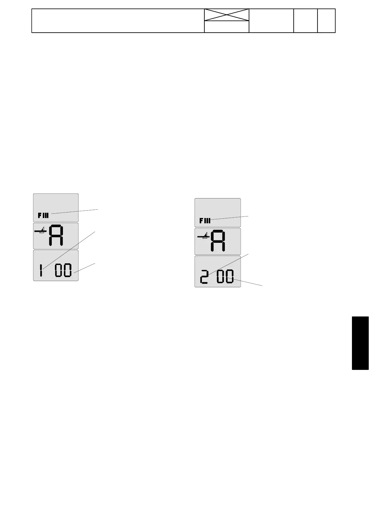
Blinking
00=calib-
ration can
be done
1=gas pedal ca-
librating mode
FIII=set-
ting mode
symbol
3. When the gas pedal calibration has been selec t ed and
confirmed (1 is visible in the LH side segment),
digits 00 start to blink in the two RH side segments (2 Hz).
This indicates that the calibrating can be done.
4. Set the mechanical gears in neut ral (engine at low idling).
Raise the engine revs evenly and gently with the throttle
lever up to max. revs during about 10 seconds, however all
the time the revs must go up. When the max. revs have
been reached, wait about 3 seconds and press the HiShift
button. At which time the control unit reads values in the
calibrating points and saves them in a memory. Lower to
the low idling speed. After the successful calibration digits
01 appear in the two RH side segments. If the calibration is
not successful, began the calibration again and raise once
again the revs slower during 12---15 seconds with the hand
gas lever. When you approach max. revs can the depres-
sing of the pedal be slowed a bit
Note! If the calibration failed (00 without blinking in the two
RH side segments ), the values are not saved and the earlier
values remain in power. In this case the calibration must be
repated. The calibrating mode is left by switching off cur-
rent.
If the calibration is not successful after several attempts or
DPS has malfunctions, (specially low rews models 6750
and 8350). Do the calibration with the computer, instr. on
page 370/19B.
If the calibration failed, so:
--- check the pump position sensor, see instr. G on page
370/24 (AC 5) or on page 371/14 (AC 5.2).
--- check the position sensor wires
--- check function of the engine speed sensor B11.See
page 370/12.
--- If the sensor and its wires areOK,thefaultmaylieinthe
control unit and it must be changed.
--- check engine speeds: lo w idling speed must be under
1000 rpm and max speed over 1800 rpm.
IMPORTANT! Escape from this mode by switching off cur-
rent.
C. Calibrating clutch pedal, AC 5 and 5.2
The clutch pedal is calibrated if:
--- test mode indicated that the pedal function is not within the
given limits
--- F a u l t c o d e A314, A315 or d225 (front controls) or A351,
A128 or d254 (reverse drive controls) appeared in the display.
--- pedal position senso r has been changed.
IMPORTANT! Before calibration, check the pedal sensor volt-
ages in AC 5, see page 370/23. When selecting the clutch
pedal calibration, the pedal must be in the upper position.
1. Activate the setting mode according to instr. A on page
370/14.
2. Select in the setting mode menu number 2 with the DPS
push buttons (in the speed gear lever knob) and confirm it
with the DPS pre ---programming button (see page 370/14)
Blinking 00=
calibration can be
done.
2=clutch
pedal ca-
librating
mode
FIII=set-
ting mo-
de sym-
bol
3. After the clutch pedal calibration has been selected and
confirmed (2 is visible in the LH side segment), two digits 00
start to blink in the two RH side segments (2 Hz). This indi-
cates that the calibration can be done.
4. Depress the clutch pedal gently and evenly to the bottom
and keep the pedal in bottom for a while, at which time the
control unit reads values in the calibrating points and saves
them in memory. After the successfully calibration digits 01
appear in the two RH side digits.
Note! If the calibration failed (01 did not appear), the values
are not saved. Old values remain in the memory and the ca-
libration must be repeated.
If the calibration failed, so:
--- check the clutch pedal potentiometer, see instr. F on page
370/23.
--- check the pedal limit switch function and adjustment.
--- Check the wires of thes e components
--- If these are OK, the fault may lie in the control unit.
IMPORTANT! Escape from this mode by switching off cur-
rent.
NOTE! Calibrate in the same way the rear clut ch pedal of the
optional reverse drive control (TwinTrac).