X13
V1, V4
1
4
7
3
6
9
2
5
8
481
Model Code Page
37. Autocontrol 5 / 5.2
1. 8. 2000
370 21
6250--8950
1. 10. 1999
P2 (Y6)
P1 (Y4)
P3 (Y17)
P4 (Y11)
P5 (Y12)
P6 (Y2)
5Nm
20 Nm
Note! Before removing valve
Y2 (P6), the temperature
switch S17 must be removed
(beside the valve).
Note! The end
of the spool
must be near
flushwiththe
valve body
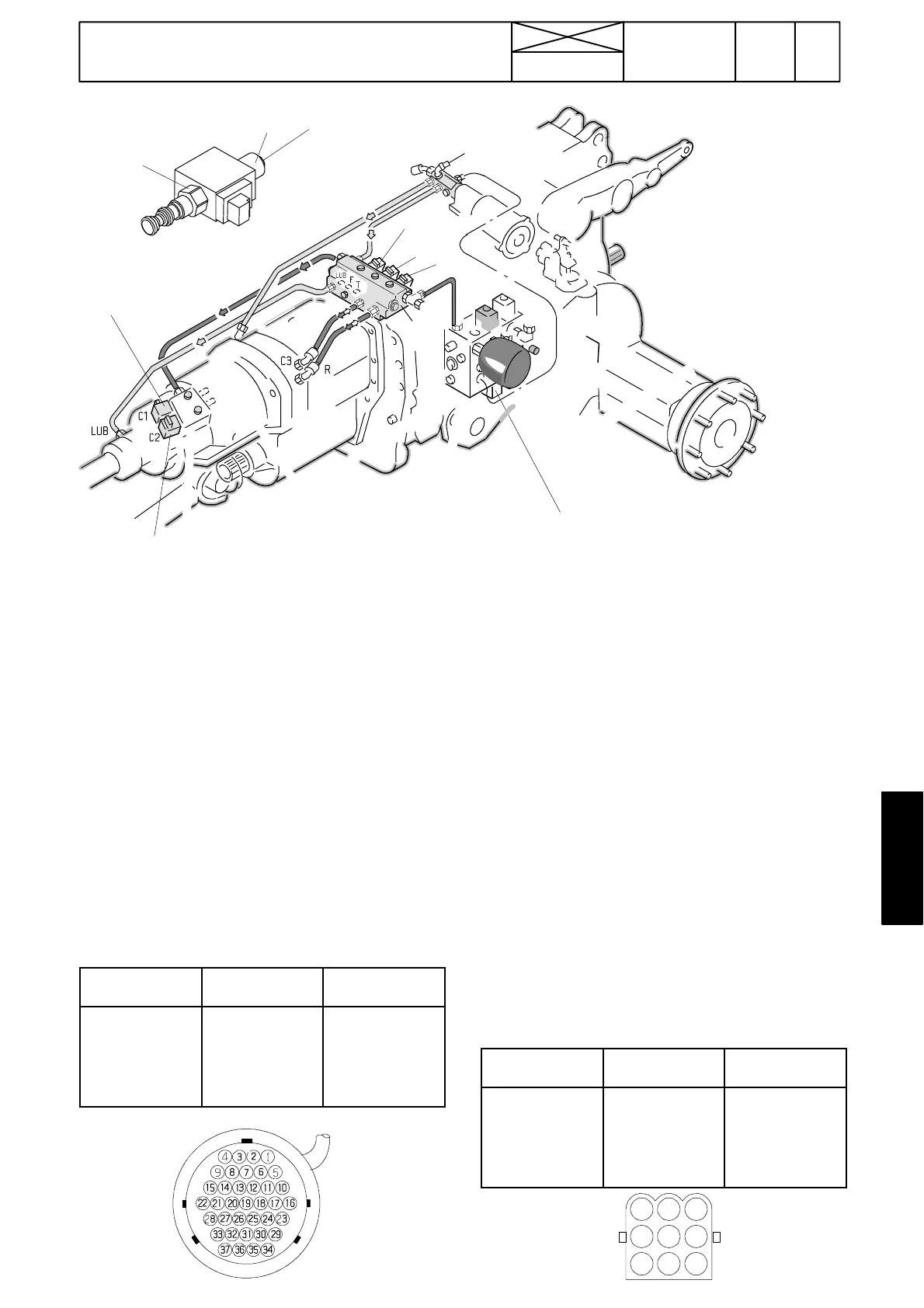
C. Proportional valves, AC 5 and 5.2
Note! The unit self ---diagnostics show a fault code, if one of
the proportional valves is faulty, see table on page 370/6
(AC 5) or page 371/5 (AC 5.2) (PTO proportional valve is
not diagnosed in AC 5). After this the valve can be tested in
the test mode. FII, see table d on page 370/13.
1. All six proportional valves are similar:
--- P1=DPS foremost clutch C1 prop. valve Y4
--- P2=DPS middle clutch C2 prop. valve Y6
--- P3=DPS rearmost clutch C3 prop. valve Y17
--- P4=forward drive (F) proportional valve Y11
--- P5=reverse dirve (R) proportional valve Y12
--- P6=PTO proportional valve (not diagnosted in AC 5) Y2
2. When the proportional valve is energised, it is magnetic
and clutch in question is pressurised.
--- P1 is energised,when DPS speeds I or II are selected
--- P2 is energised, when DPS speeds I or III are selected
--- P3 is energised, when DPS speeds II or III are selected
--- P4 is energised when forward drive is engaged
PINS (X13)
SOLENOID RESISTANCE
(+10...+30 ˚C)
2<>5
4<>5
7<>5
11<>5
12<>5
13<>5
Y2 (PTO)
Y4 (C1)
Y6 (C2)
Y17 (C3)
Y11 (F)
Y12 (R)
7 --- 9 o h m s
--- P5 is energised when reverse drive is engaged
--- P6 is energised when the PTO is engaged.
3. The resistance of the proportional valves is measured
from connector X13 pins. Correct value is 7 --- 9 o h m s
(+10˚ C...+30˚C).
4. If the resistance is incorrect, the valve solenoid is
changed. After this the valve indexes must be set, see instr.
on page 370/24D.
5. If the resistance is correct, but in the circuit there are mal-
functions, check the valve wires and connectos. If these are
OK, perform the calibration of the initial pressure. Also the
diodes must be checked in AC 5 according to table below
(in AC 5.2 the diodes are placed in the control unit A1).
Note! Onepossibleandcommonfaultisimpuritiesinthe
valves. This can cause faults which are very difficult to find.
If you doubt this fault, change the proportional valve or try
to clean it.
6. If the valve and its wires seem to be OK, but malfunc-
tions exist, the fault can lie in the control unit.
Note! During repair check (before engine start) that the
valve spool end is nearly flush with the valve body.
Diode test with multimeter, AC 5 only.
SOLENOID
DIODE HOU-
SING (V1, V4)
PINS (V1, V4)
Y2
Y4
Y6
Y17
Y11
Y12
V1
V1
V1
V4
V4
V4
2<>5
9<>8
7<>8
9<>8
7<>8
3<>6