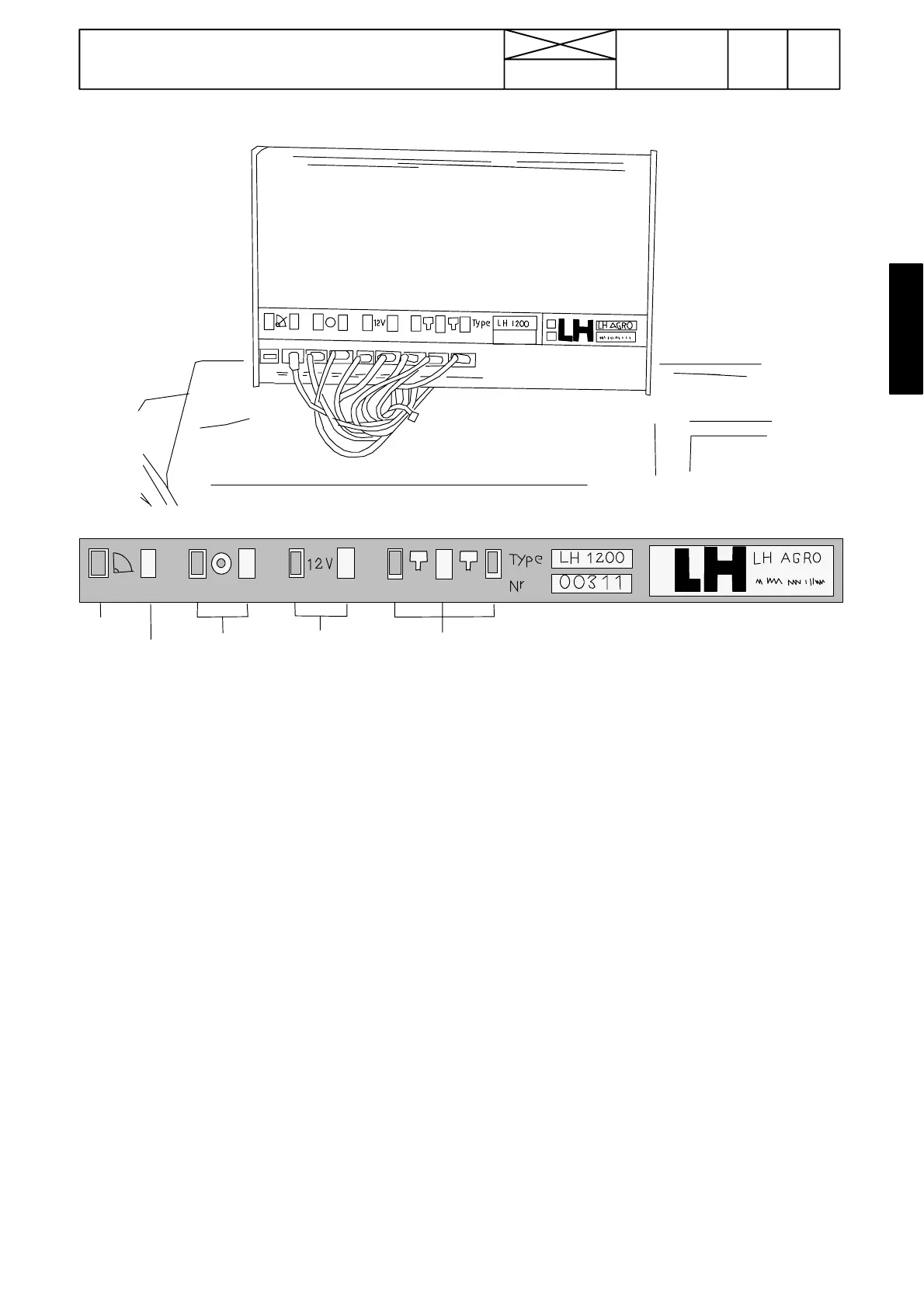
Lift/lower
switch
Wheel
sensor
Supply
voltage
Implement sensor
RPM sensor
Earth
327
Model Code Page
33. Valmet Agrodata
8. 11. 1990
6000--8400 330 3
123456 789
123
4
567
8
9
+---
+---
---
sign.
sign.sign.
---
Figure 3. Cable terminal panel (monitor unit rear panel)
Terminal 1; earth (no lead)
Terminal 2; Signal from lift/lower switch of power lift
Terminal 3 and 4; Wheel sensor leads
Terminal 5 and 6; Supply leads (battery voltage)
Terminals 7, 8 and 9; Leads for sensors on implement (or en-
gine RPM sensor leads)
Note! Sensors on implement can be e.g. flow meter, piece
counter, RPM sensor etc.
1. Trouble shooting
A. Checking display operation
The Agrodata unit receives its power supply from connector
X55 (in the lever console).
1. Turn on the ignition. Check that:
--- the monitor display is lit
--- the display flashes the word ”AGRO”.
2. If this does not happen:
--- check fuse F17 (10 A) in the fuse box
--- disconnect the monitor (not the leads) and make sure that
the unit is receiving power (measure voltage between ter-
minals 5 and 6.
3. If the power supply is in order, but the monitor fails to oper-
ate, the defect is in the unit itself. In this case the monitor must
be replaced (the condition of the other leads and sensors is
irrelevant if the monitor is defective).
4. If the monitor responds to commands (e.g. working width,
wheel circumference), it is in working order.
5. If the monitor displays or flashes the word ”FEJL”, this indi-
cates that the supply voltage to the unit is not adequate (12 V).
Check the condition of the battery and the battery connec-
tions.