Outdoor temperature ˚C
Nozzle temperatures ˚C
1145
Model Code Page
83. Air conditioner
1. 1. 1994
6000--8750 831 3
15. 5. 1993
1. Fault tracing without special
equipment
Note! This instruction supposes that the outdoor temperature
is high enough so that the temperature switch switches on the
compressor.
A. Correct function
When the air conditioner is functioning properly the com-
pressor runs and stops at regular intervals and cool air flows
into the cab according to the position of the temperature
switch.
To check for malfunction, carry out the following simple test in
the shadow by fitting a thermometer sensorinto the frontven-
tilation nozzle on the LH side and by following nozzle tem-
peraturesduring 5---10 minutes. During thistest the windows,
doors and re---circulation nozzles should be closed. Select
the max speed for the fan. Adjust the max cooling effect and
set the engine revs to 1500 RPM.
Nozzle temperatures should be according to the curves
below (±1,0˚C). Curve A is for the earlier air conditioner and
curve B for the later air conditio ner which has the roof console
on the RH side of the roof:
20 22 24 26 28
12
14
16
18
20
30
10
A
B
If measured temperatures agree with the curve above, the air
conditioner is in order.
If the nozzle temperatures are higher, make sure that the
heater contro l knob is closed so that the warm engine coolant
does not circulate in the heating element which is placed in
front of the evaporator. If the knob is closed, see the following
instruction B .
B. Refrigerant filling and moisture
--- Check the amountof refrigerant and moisture in the system
through the drier inspection gl asses (see page 831/2).
Moisture in the system causes icing in the expansion valve
and in the compressor which in turn causes malfunctions.
Refrigerant+water causes a corrosive compound.
P ossible leakages can be found with an electronic leak
detector. If the refrigerant filling is wrong or there is moisture
in the system, contact an expert who knows refrigerating sys-
tems. If everything is OK, see the following instruction C.
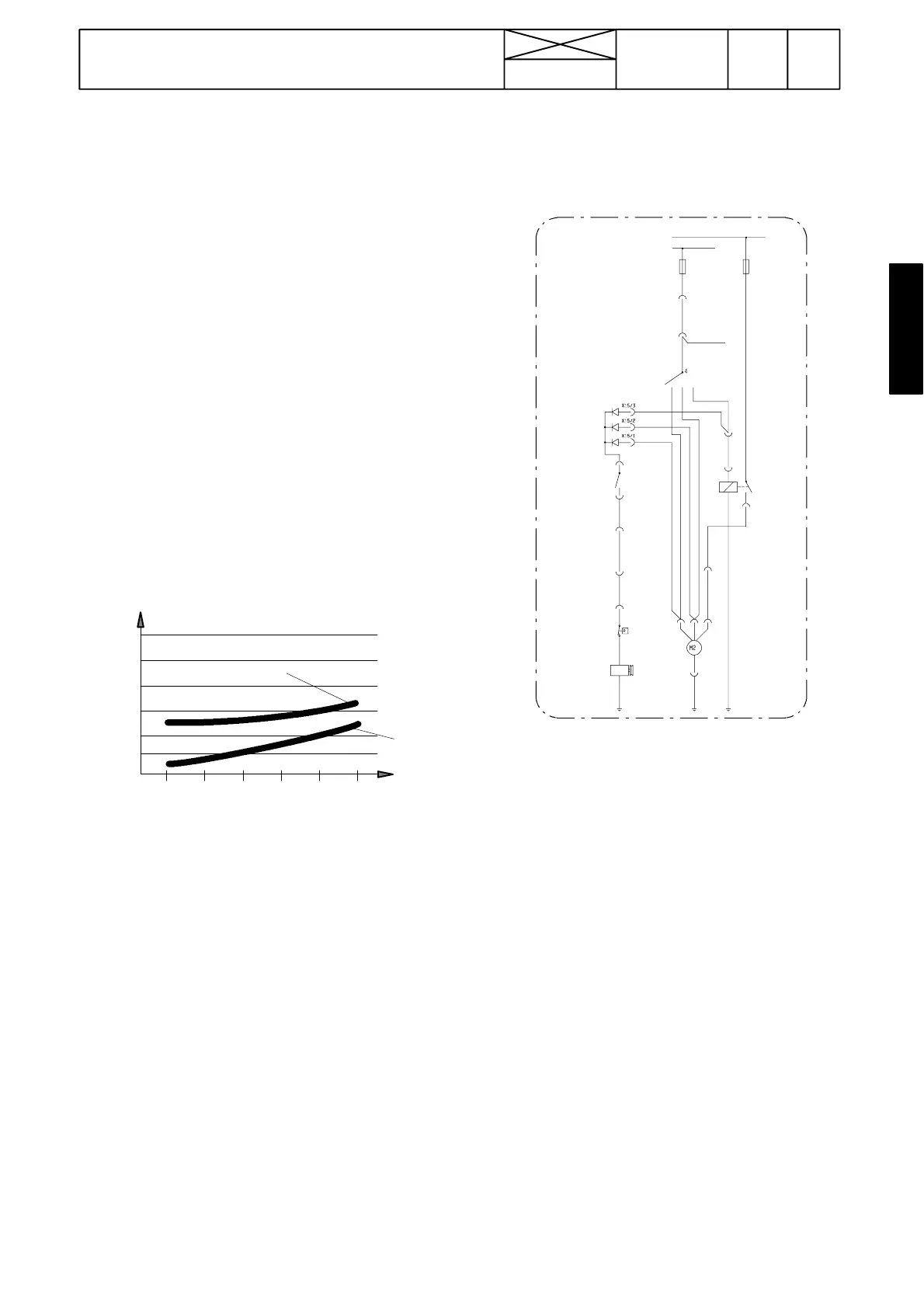
C. Electric system
S3
K6
S8
S19
Y5
M2
X15
234
1
1023
30
15
18KE
F21
F15
18KE
4VI
3RU
38LI
X5/1
38LI
X24/6
38LI
X24/4
18KE
X7/3
70MU
X7/1
X24/5
70MU
X11/9
X19/8
93MU
93MU93MU
2
1
Switch on current to the tractor and turn on the fan S3. If the
fan does not start, check fuse F21. If the fan started, turn the
temperature switch S8 to max cooling effect at which time the
click---sound must be heard from the compressor magnetic
clutch. This indicates that the electric system functio ns.
If the click---sound was not heard, disconnect the wires to the
pressure switch S19 and connect the wire ends (never con-
nect the + wire to the frame). If the click can now be heard in
the compressor, the electric system is OK, but the fault lies in
the pressure switch or in the system pressures. Call an expert.
If the click---sound cannot be heard when connecting the
pressure switch wires, check the supply wire for current to the
pressure switch. If it is there , the fault lies in the compressor
magnetic clutch or in its wiring.
Measure the voltage from the pressure switch supply wire
with different fan speeds. If there is no current with some fan
speed, the fault lies in diodes, which should be changed. The
diodes cannot be changed separately but the complete wir-
ing set no 326 107 00 (earlier air conditioner) or no 328 351 00
(later air conditioner) sho uld be changed.
If there is no current to the pressure switch wire, check con-
nector X19/8 in the cab front wall on theRH side and alsocon-
nector X11/9 which is placed behind the roof panel in the cab
(on the RH side).
If there is no current to the pressure switch wire, connect the
temperature switch wire ends. If now there is current to the
pressure switch supply wire, the fault lies in the temperature
switch which should be changed.