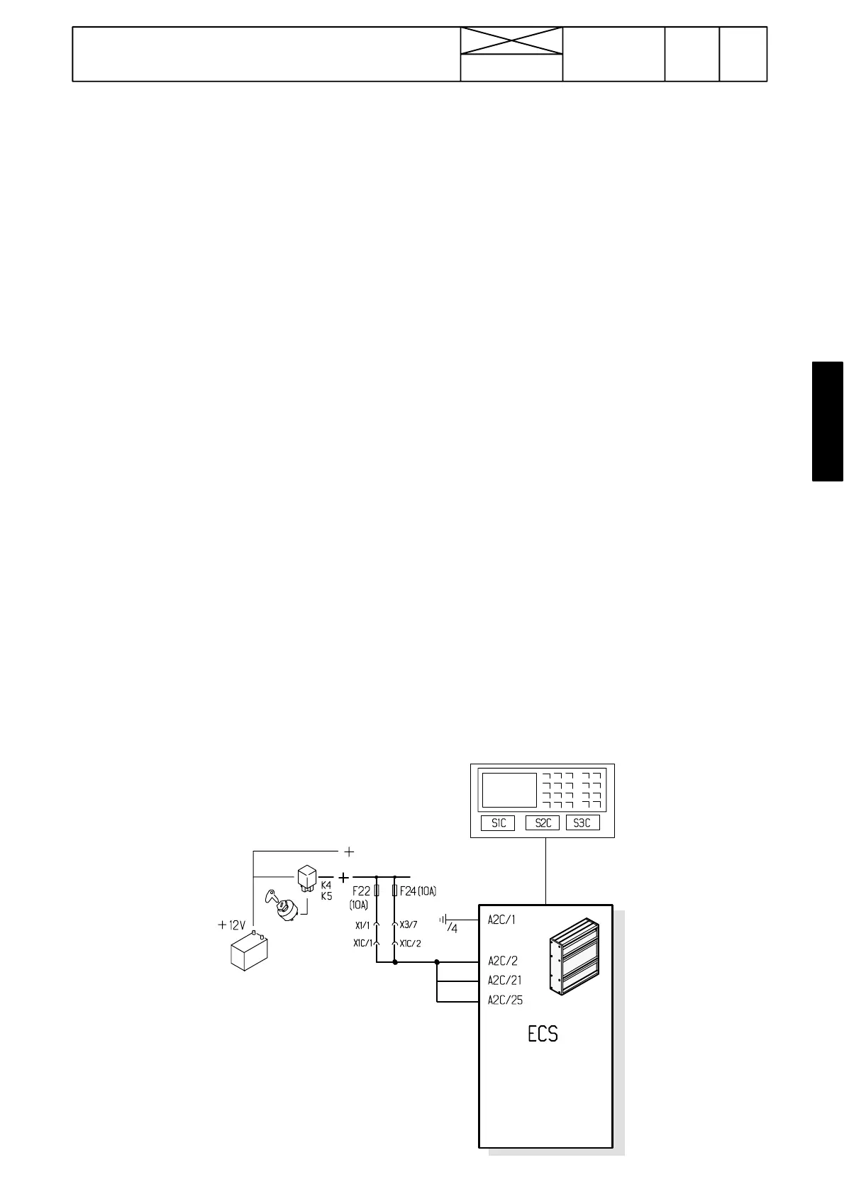
Figure 1. Supply voltages
365
Model Code Page
34. Autocontrol ---III
8. 11. 1990
6600E, 8100E 341 3
15. 6. 1992
2. Fault tracing without microcom-
puter
A. Manual fault tracing
(Computer ---aided traouble shooting, see Code 342)
Manual fault tracing is based on the functional checks and
possible malfunctions which are found in these checks (see
pages 341/4---7 later in this section).
A possible malfunction can then be localised by measuring
with a voltmeter voltages or resistances from the pins of the
ECS connectors A1C (lower) and A2C (upper). Connector
pins have been numbered on the connectors.
Inputs
Input signals for controlling the transmission can be
measured from the connector A2C. The measurements are
carried out according to the fault tracing tables in instruction
under code 342 (computer ---aided trouble shooting).
Switches and pedals must be in the positions given in the
tables. If no input signal comes, check the switch in question
and its wiring.
Input signals from various sensors can be checked by means
of resistance measurements according to the instruction 1
A --- H above.
Outputs
Output signals for controlling the transmission can be
measured from the pins of connector A1C. The pins must
have loading when measuring (e.g. test pen). Here must also
be used the tables under code 342. If a correct output signal
comes, but the tractor does not function, check a solenoid
valve and an indication light in question and their wirings. If
output signal fails to come, the ECS is faulty. Output signals
into the implement socket, see page 342/9.
A. Supply voltages
--- Switch on current to the tractor
--- I f V a l m e t --- n a m e a n d t i m e a p p e a r s o n t h e A C I I I d i s p l a y, t h e
unit is in order.
--- If nothing appears on the display, check the AC III unit fuses
in the fusebox: F22 (10 A) and F24 (10 A).
--- If the fuses are OK, disconnect the ECS upper connector
A2C and measure supply voltages: pin 1 (earth), pin 2 (sup-
ply), pin 21 (supply) and pin 25 (supply).
--- If there are not supply voltages, check supply voltage wir-
ings and connectors.
--- If there are supply voltages, the central unit ECS is faulty or
the display unit is defective.
B. ECS (central processing unit)
If the AC III display unit only flashes and then switches off
when the current is switched on, the ECS is faulty and should
be changed.
If the ECS uses always the default parameter file although a
correct file is input with a microcomputer, the ECS is faulty
and should be changed.
When You are programming the AC III unit with a microcom-
puter and message ERROR IN EPROM appears in the mess-
age window, switch off current and start from the beginning.
If the same message appears, the ECS should be changed.
When You measure output signals from the ECS, the lacking
signal indicates that the ECS is faulty and must be changed.