395
Model Code Page
35. Autocontrol IV
15. 5. 1996
6600E
8100E-- 8750E
350 11
1. 1. 1994
Position of connectors
See picture 7 on previous page.
The ECS connectors A1C (red) and A2C (see also page
350/9) are placed in the cab lever console on the driver’s right.
In the lever console, there are also the following connectors:
--- X1C: ECS supply and solenoid valve wires
--- X2C: speed sensors and radar wires
--- X3C: implement socket wires
--- X5C: switch and sensor wires
--- X6C: power lift control panel wires
--- X7C: power lift wiring loom connector
In front of the lever console under the panel:
--- A10: Delta Power Shift control unit A10 connector
--- S23: Power Shift push button connector
--- X23: connector for extra push buttons
All speed sensor pins are equipped with connectors. The
radar connector B7C is located near the radar.
Sensors in the engine compartment:
--- the outdoor temperature sensor connector is fitted in the
frontpartofthetractor.
--- the engine temperature sensor pin has a connector.
--- the front wheel steering angle sensor connector S4C is
located on the right hand side of the engine
--- X4C: connector for sensors in the front part of the tractor
--- fuel injection pump potentiometer connector B8C.
--- Y8 is a starting solenoid on the fuel injection pump
Note! All wires from the sensors in the engine compartment
are drawn via socket X19 in the cab front wall on the RH side.
The solenoid valve connector X13 is placed under the hand
brake lever console on the driver’s left. In addition, the sole-
noid pins have connectors:
Y1=Diff. lock solenoid
Y2=PTO solenoid
Y3=4WD solenoid (energised when 4WD is disengaged)
Y4=Delta Power Shift, reduction ratio
Y6=Delta Power Shift, overdrive
In the direct ratio, both solenoid valves are energised.
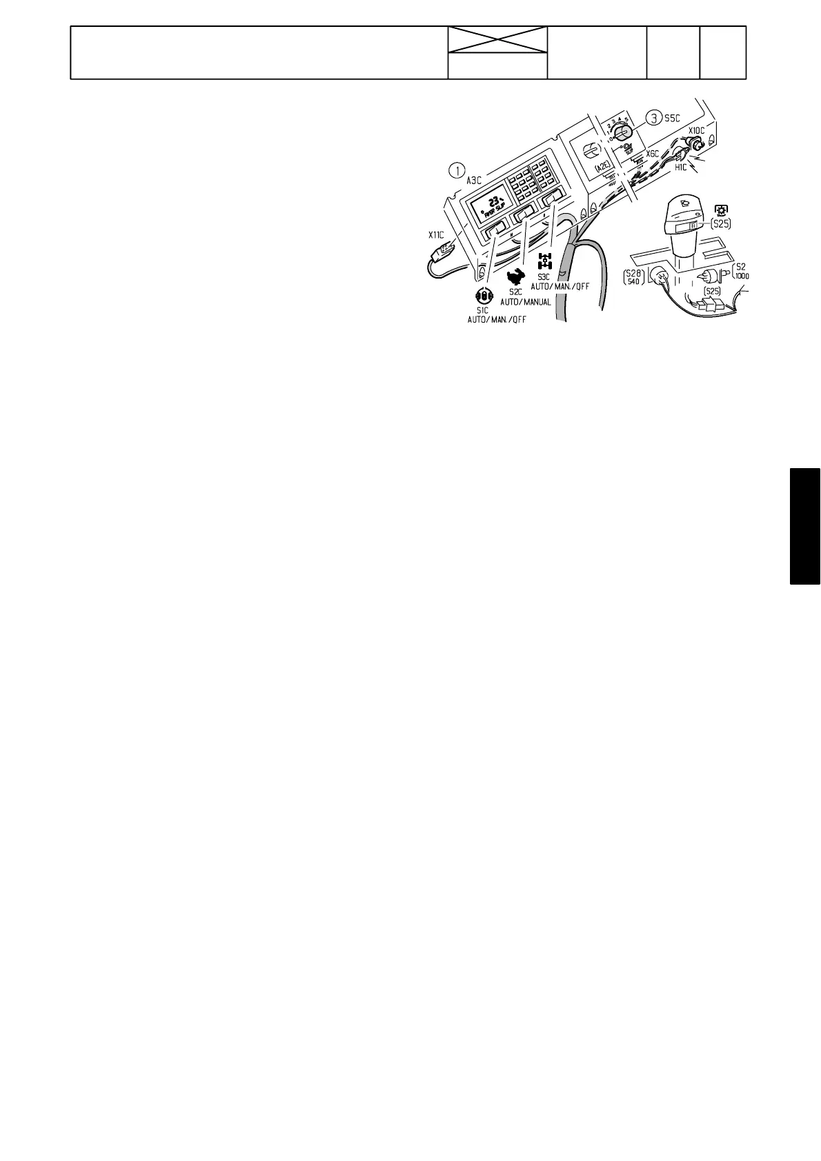
Display unit (1), A/M ---switches, power lift controls and slip
control selector (3) and slip control buzzer (H1C) are access-
ible after unscrewing the panel cross---head screws. The
panel has two sections.