S7E S8E
S9E
S7E
S8E
S9E
1
12
A2E
A
1
12
Connettore
296
Model Code Page
32. Electro---hydraulic power lift
15. 4. 1995
6000--8400 320 10
8. 11. 1990
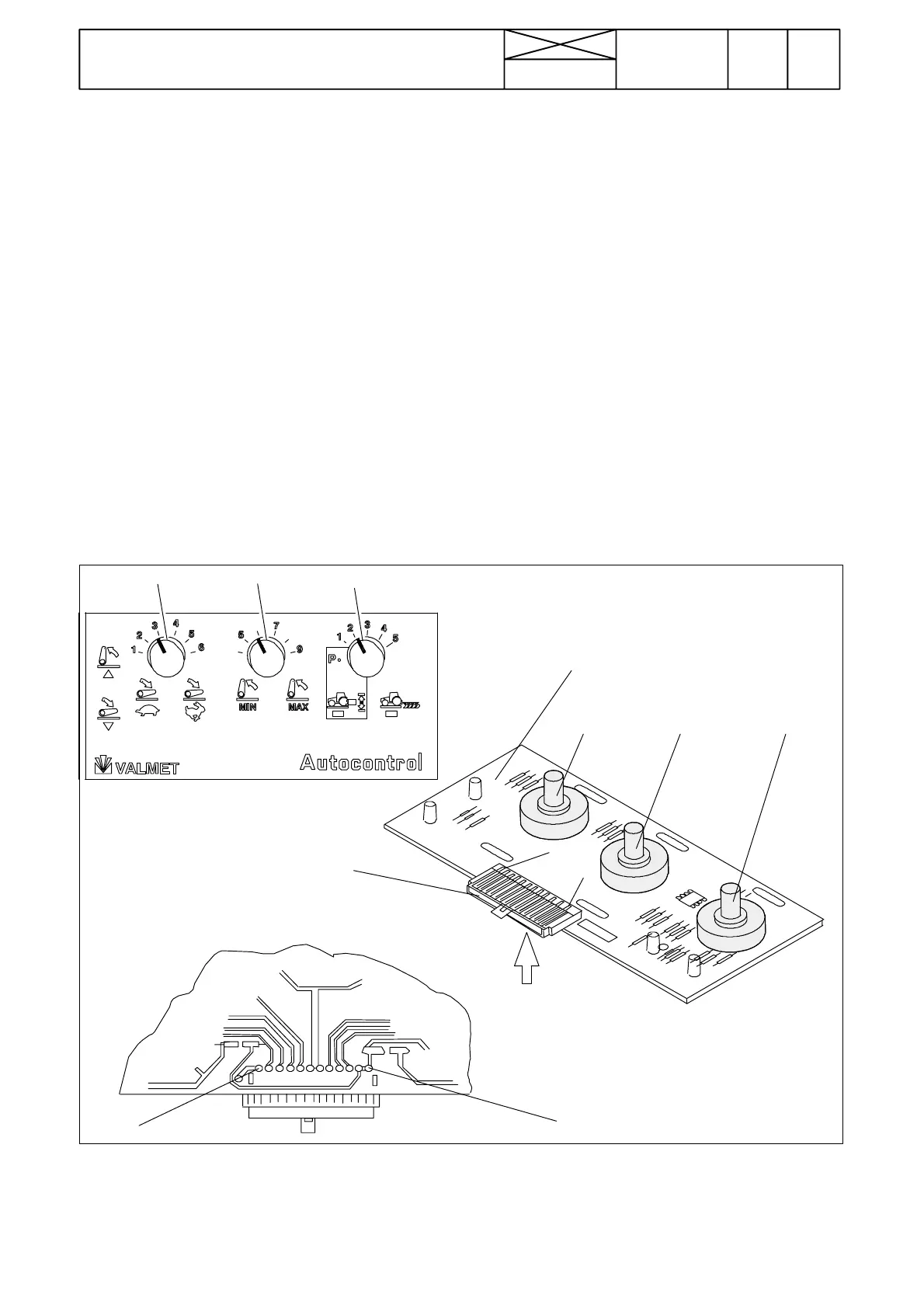
1. Checking switch panel A2E
If lowering speed (S7E), transport height (S8E) or draft control
selector (S9E) does not function properly and the malfunction
cannot be localized with the help of the preceding instruction,
the switch panel A2E can be checked as follows:
N.B.! In the checking, a voltmeter (measuring scale 0---14 V
DC) is needed. The voltmeter measuring heads should have
sharp ends so that they can be pricked through protective lac-
quer.
Measurements are done on the tinned terminals on the rear
side of the switch panel. Measurements are done without de-
taching the connector from the panel.
A. Removing the switch panel for check-
ing
1. Detach the bracket on which the switch panel is fitted by un-
screwing four crosshead screws.
Note! On E ---models and on models equipped with Agrodata,
the switch panel and its bracket is fitted more to the rear on the
lever console.
2. Turn the bracket/switch panel so that voltage measure-
ments can be done according to instruction B.
3. Turn the current on with the ignition switch and activate the
control system with the lift/lower switch. Do not detach the
connector from the switch panel.
Note! From serial no 668103 incl. (AC 2.1), there is the DPS
circuit card fitted on the power lift switch panel. Remove, if
necessary, this circuit card before measuring the power lift
voltages.