Shock valve (20 MPa)
1247
Model Code Page
90. Hydraulic system
8. 11. 1990
6000--8750 912 1
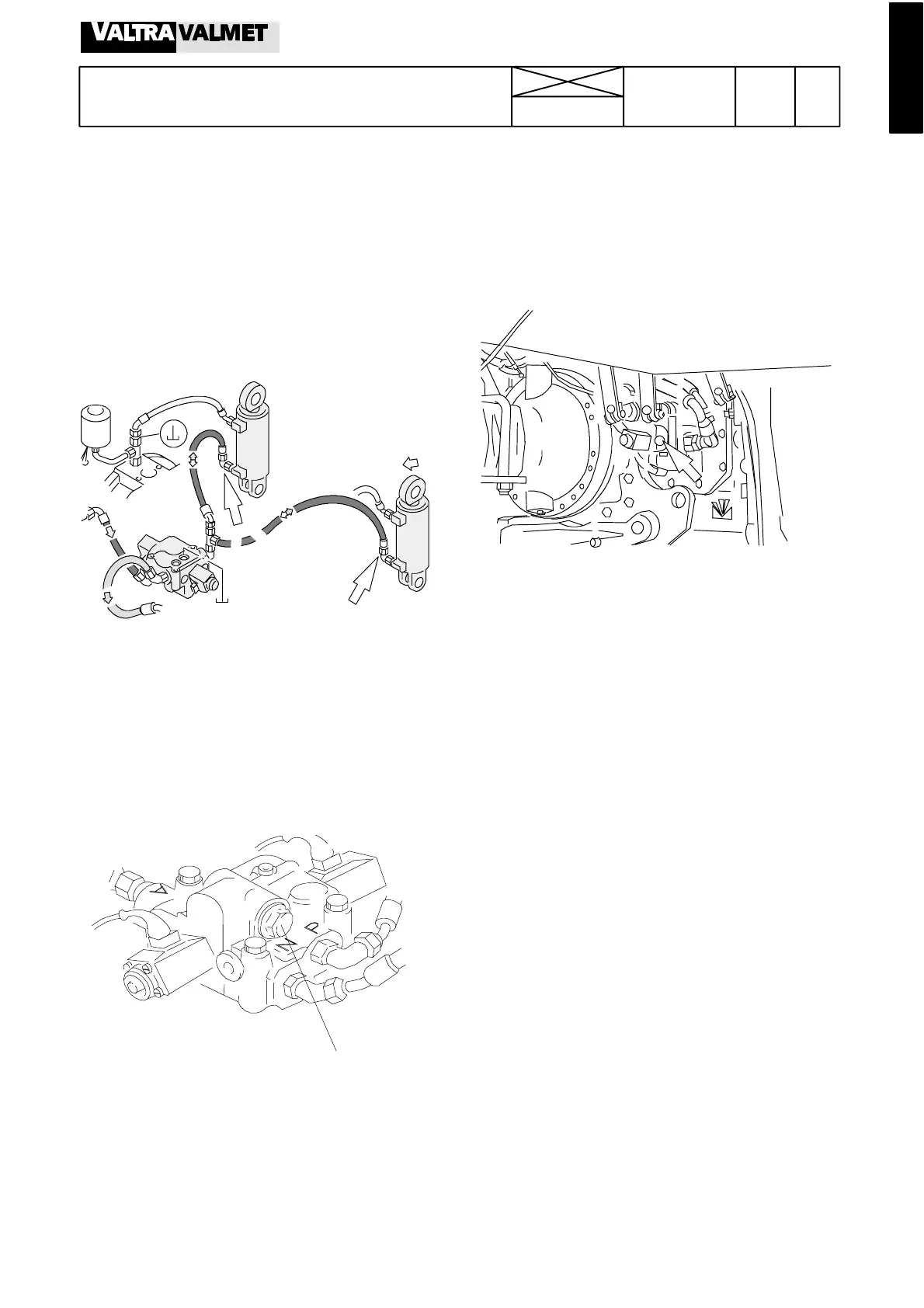
Hydraulic power lift
1. Control valve
A. Checking shock valve opening pres-
sure
1. Lower the lower links to the lowest position.
2. Connect a pressure gauge and a hand pump to one pres-
sure hose of the lifting cylinder (see arrows) (measuring
equipment, see page 910/5).
3. Raise the lower links to the upper position, stop the engine
and switch off current.
4. Pump with the hand pump pressure into the control valve
and read the opening pressure, which should be 20 ---21
MPa.
Note! The shock valve is accessible without removing the
control valve.
Note! If you want to lower the lower links without s tarting the
engine (e.g. during repair work), unscrew the shock valve
after which the lower links can be pressed to the lower posi-
tion.
B. Removing control valve
Note! The control valve is fitted on the RH side of the gearbox
housing.
1. Remove the RH side rear wheel. Disconnect the so l enoid
valve leads from the control valve.
2. Disconnect all oil hoses from the control valve. Unscrew the
control valve fixing bolts (3 pcs) and remove the valve.
Note! There is an oil hole between the control valve and the
selector cover. This hole has been sealed with an o---ring,
which must be fitted back when the control valve is fitted.
C. Fitting c ontrol valve
1. Make sure that the o---ring is in place between the control
valve and the selector cover.
2. Fit the control valve and tighten the fixing bolts evenly to
23---27 Nm.
3. Connect the solenoid valve leads and all oil hoses.
4. Test---drive the tracto r and check the function of the hy-
draulic power lift.