379
Model Code Page
34. Autocontrol ---III
15. 6. 1992
6600E, 8100E 342 9
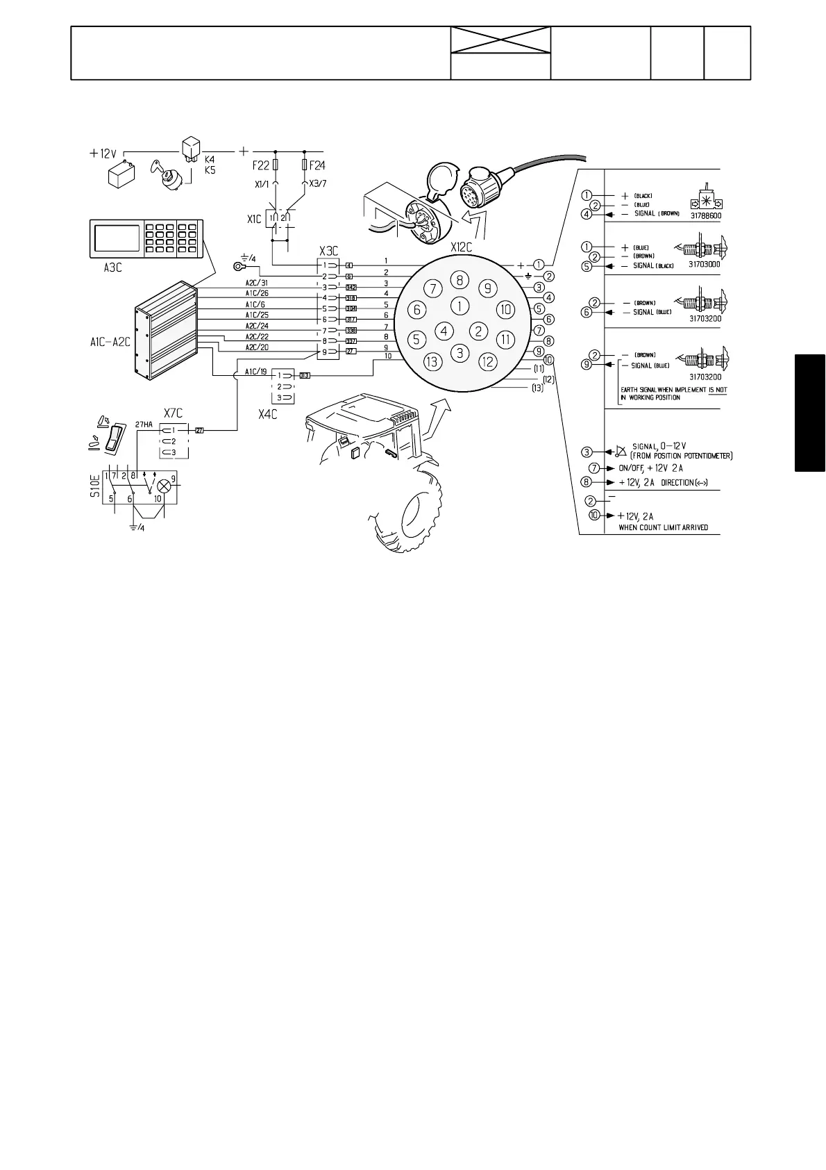
AC---III, implement socket
Implement sensors
Flow meter
RPM sensor
Piece counter
Working position
Signals for controlling
linear actuator
When the limit of count is reached
Checking line from implement socket to
A C --- I I I u n i t
--- Switch on current to the tractor
--- Measure the supply voltage between socket terminals 1
and 2 (= battery voltage, about 12 V DC).
--- Connect a microcomputer to the AC---III unit and activate
the trouble shooting chart (see page 341/1).
FREQUENCY INPUTS
1. Shunt between socket terminals 2 and 4 (break connec-
tion). A number signal must appear on the PC at point Flow.
This function is the same as the flow meter paddle wheel
would revolve. Also AC---III display shows some value in the
liquid amount mode (litres).
2. Shunt between socket terminals 2 and 5 (break connec-
tion). A number signal must appear on the PC at point RPM
impl. Also AC---III display shows some value in the implement
RPM mode. This function is the same as a magnet would
pass by the sensor.
3. Shunt between socket terminals 2 and 6. A number signal
must appear on the PC at point PCS every time the connec-
tion is broken off and on (summing counter). Also AC ---III dis-
play shows in the piece counter mode the same value. Note
possible limiting program, which limits the max number of
items. When the limit value is achieved a signal (0 changes
to 1) appears at the point Pieces counter (DIGITAL OUT-
PUTS). This signal can also be measured with a voltmeter
between socket terminals 2 and 10. This function is the same
as a magnet would pass by the sensor.
DIGITAL INPUTS
4. Activate the hydraulic power lift and turn the lift/lower switch
to the lowering position. Shunt between socket terminals
2and 9. A signal (1 changes to 0) appears on the PC at point
Implement pos. When the socket terminals are connected
the arrow on the AC---III display turns to point upwards. The
function is the same as a magnet would be opposite the sen-
sor. The lift/lower switch has the same function.
ANALOG INPUTS
5. Signal from possible position potentiometer: Shunt
between socket terminals 1 and 3, after which a number sig-
nal appears on the PC at the point Implement pot
. Here with
battery voltage the signal is about 250. Also AC---III display
shows some value (e.g. 100) in the implement position mode.
Signals to linear actuator
--- connect an adjustable resistor to the socket poles 1 (+:
black), 2 (---: Red) and 3 (sign: Yellow).
--- calibrate the resistor’s extreme positions (e.g. 0 (P1) and
100 (P2)).
--- input 5 pcs pre---programmed resistor positions (e.g. 10,
30, 50, 70 and 90)
--- move the resistor spindle inwards and outwards in the
middle range and check that the output signals appear on the
PC with e.g. the pre ---set position 50. Implement dir (current
to a relay for controlling actuator rotation direction; 0 or 1) and
Implement act (current to a relay for controlling actuator; 0
or 1) (both DIGITAL OUTPUTS)
By connecting a test lamp to the socket poles 7 or 8 (earth
from any frame contact) it can be checked if the current
actually comes to the socket.
N.B. If the line from the socket does not function, check con-
nectors X3C and X4C (in the lever console). Check also wire
connections in the socket. If the output signals do not come
the ECS is faulty.