254
Model Code Page
31. Σ --- p o w e r s y s t e m
1. 10. 1999
8750, 8950 313 2
1. 6. 1999
1
2
2
3
5
6
7
1
337 450 00
2
34008010
34008110
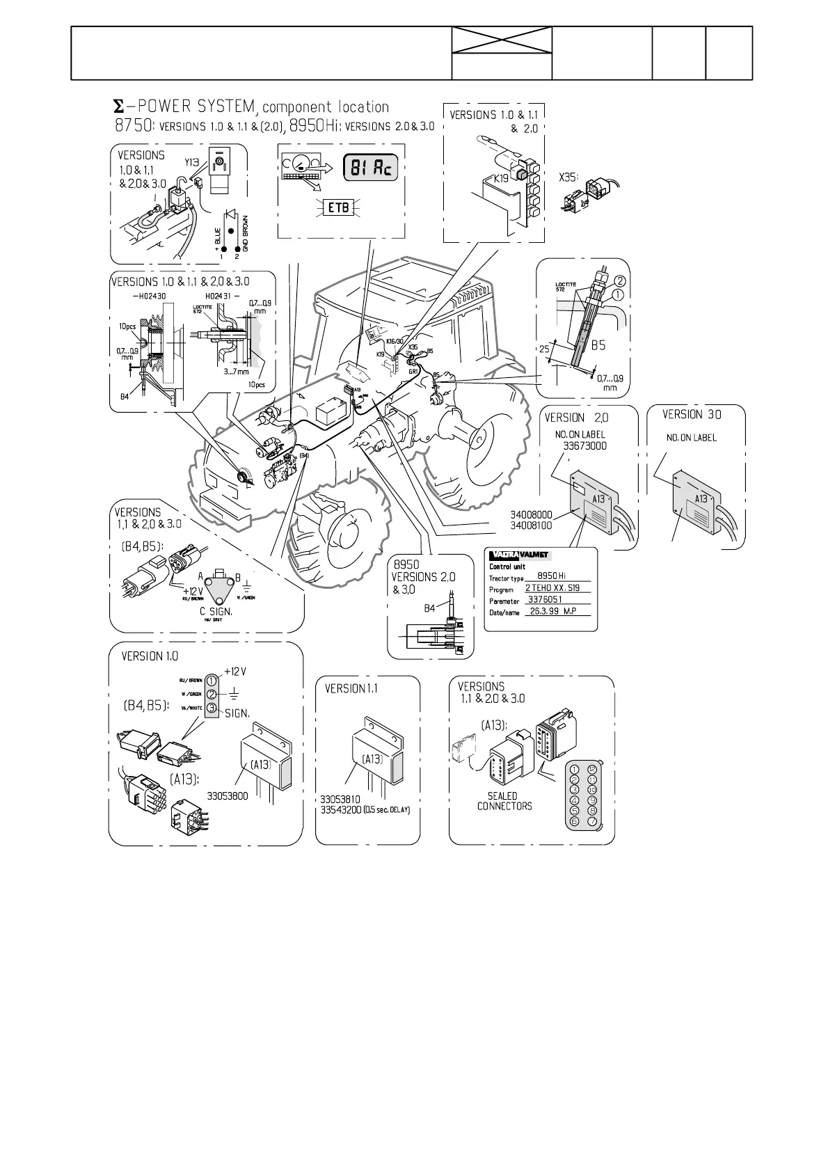
Picture 1. Components for Σ ---power system
1. Engine speed sensor B4
Note! On 8950Hi tractor the engine speed sensor is placed
at the front end of the DPS
2. Σ ---Power control unit A13.
Note! Modifications have been ma de in th e control unit, when
new versions have been started to use. Different versions are
showninthetableonthenextpage313/2A.
3. PTO speed sensor B5
4. Boost control unit on the fuel injection pump governor
housing (see page 313/3).
5. Solenoid valve Y13.
6. ETB---light and output % display
7. Σ ---Power relay K19 in the lever console in the cabin (not
in version 3.0)
Po sition of connectors
--- connector X35 (9 pins) is placed in the lever console and
it is accessible after removing the console side cover.
--- Sensor B4 connector in the engine compartment.
--- Sensor B5 connector has been drawn into the lever con-
sole.
--- Control unit connector A13 (12 pins) in the engine com-
partment near the control unit
--- Control unit A13 earth point GR9 in the cab front wall
--- O t h e r Σ ---Power earth point GR1 in the cab lever console
rear part
--- Relay K19 is placed in the lever console beside the
relays for the AC 2.1 unit (not in version 3.0).