650
Model Code Page
41. Clutch
1. 4. 1997
6000--8750 411 2
15. 5. 1993
8. Remove the propellershaft guard under the tractor and dis-
connect the front flange joint of the propeller shaft.
Important! On tractors with Delta Powershift, the front flange
joint is unnecessary to disconnect , since the rear end of the
propelle r shaft has a splined sleeve joint.
9. Unscrew the bolted frame joint at the clutch. Disconnectthe
windscreen washer hose and the cable connector.
10. Carefully push the front frame apart from the middle frame
about 40 cm.
11. Tap the clutch shaft bac kwards until its front end loosens
from the bearing. Push the pump drive shaft backwards until
its rear end splines engage.
Note! This is done to prevent damage to the seal inside the
hollow input shaft.
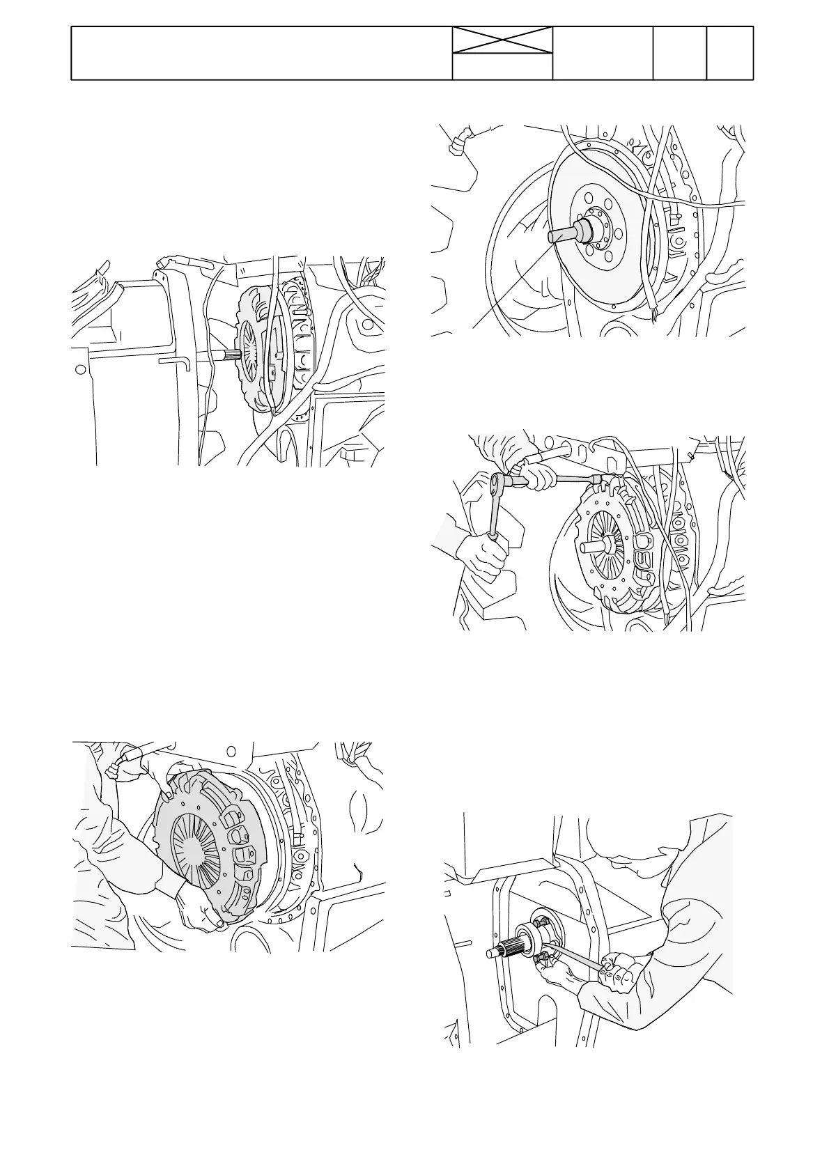
B. Changing clutch/disc
1. Split the tractor at the clutch (see instr. A).
2. Unscrew the clutch fixing bolts evenly and remove the
clutch assembly/disc.
3. Check the condition of the clutch shaft front end bearing.
Check also splines on the pump drive flange on the flywheel.
Note! On the hydraulic coupling models the coupling mustbe
detached before checking the pump drive flange.
ETV 893790
4. Fit centring too l ETV 893 790 and place the disc onto the
centring tool (disc hub longer side rearwards).
23 Nm
5. Fit the clutch assembly and t ighten it evenly to a torque of
23 Nm. Remove the centring tool.
6. Assemble the tractor (see instr D). Adjust the pedal free
travel (see instr 2A).
C. Changing release bearing
1. Split the tractor at clutch (see instr A).
2. Prise out the bear ing/tube and plac e 40 mm long bolts be-
tween the bearing and guide sleeve.
Important! Changing the release bearing with effect from
tractor ser. no. 659478, see page 411/10.