257
Model Code Page
31. Σ --- p o w e r s y s t e m
1. 8. 2000
8750, 8950 313 3
1. 10. 1999
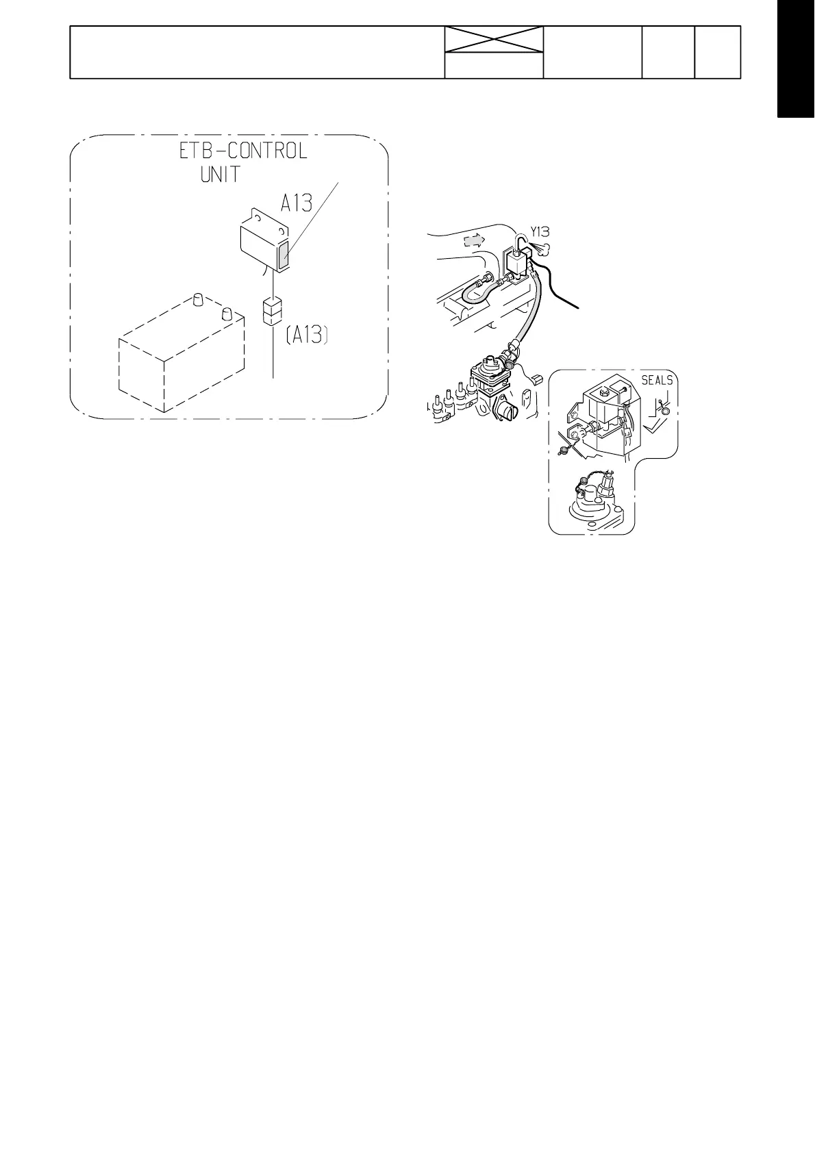
B. Control unit A13
Marking
dot
The control unit is situated in the engine compartment.
Function
The control unit gathers information from the sensors and
switches and sends required electric signals to the solenoid
valve and the pilot lights in order to switch on/off the higher
engine output range.
The torque of the PTO unit should be at least 2 sec. (0,5
sec. in versions 2.0 and 3.0) above the switch ---on torque,
before the higher output range is switched on. This elimin-
ates malfunctions caused by occasional torsional vibra-
tions, e.g. during starting. When the PTO unit torque
decreases, the torque should be at least 5 sec. below the
disengagingtorquebeforethelowerenginetorquerangeis
switched on. Thus e.g. a sudden loading decrease in the
PTO unit (e.g. at occasional holes or puddles etc.) does
not disengage the higher output range. In addition, the dis-
engaging torque is a little lower than the engaging torque.
These differences in the times and torques also prevent
possible seesawing engagements.
Note! The engaging torque has been changed, see table
on page 313/2A.
If the ETB light does not light or flash, although the PTO is
loaded so that the higher output range should engage and
the digital instrument does not show the percentage value
of the PTO output (e.g. the instrument shows 99 Ac or 0 Ac
regardless of the loading of the PTO unit), this indicates that
the system has been damaged, see fault tracing on pages
313/6---13.
If there are malfunctions in engagements between the two
output ranges (e.g ETB---light blinking), the control unit may
be damaged or the sensors have faulty adjustments.
Spare part control units have been programmed in the fac-
tory and they can be fitted in place of the damaged units
(connectors are supplied with the unit). If the control unit
A13 has to be changed, the solenoid valve seal must be
broken.
IMPORTANT! If on 8750 tractor is fitted the control unit of
version 2.0 in place of the versions’ 1.0 or 1.1 units, con-
nector A13 wires to pins 4, 7 and 12 (on tractor wire loom
side) must be disconnected and the ends of the wires must
be isolated (if not made earlier)
C. Solenoid valve Y13 and boost control
When voltage of 12 V is fed to the solenoid valve pins, the
valve should become magnetic and ”click” must be heard
from the valve. Always when the ETB light illuminates, the
solenoid is energised (higher output range is on).
Seals:
To prevent overriding of the solenoid valve or supply direct
to the solenoid pins, lead seals have been made on the
solenoid valve and on the boost control pipe, see picture
above.
If the solenoid valve has to be changed during the warranty
period, the sealing must be done anew. If the control unit
has to be changed, the solenoid valve seal must also be
broken. If a tractor fails due to the overriding of the control
unit, the warranty does not compensate the costs.
Note! The function of the boost control has been described
on page 223/9, which deals with 6800 tractor, but the func-
tion is the same as on 8750 and 8950 tractors, when the
solenoid valve is energised (open).
The ETB ---light indicates, if the solenoid valve is not func-
tioning, ETB---light then flashes in time 2sec*) on and 0,5
sec off. This flashing indicates that the solenoid valve con-
trol is not on due to e.g. a short circuit or there is no load in
the solenoid output pins, e.g. solenoid wire broken.
*) 1 sec. in versions 2.0 and 3.0.