345
Model Code Page
33. FieldMaster
1. 8. 2000
332 76200--8950
1. 8. 1998
4. Baler
TEST INPUT
RADAR
0HI
PTO
0HI
WHEEL
TRACTOR
0HI
DIESEL
0HI
IMPLEM.
0HI
TRAIL. 1
0HI
TRAIL. 2
0HI
TRAIL. 4
LO
TRAIL. 7
0LO
TRAIL. 8
0LO
BOMTEST
OK
TRAIL 1: Signal from a piece counter, when the sensor is
activated.
TRAIL 2: Signal from the rpm sensor (RPM 3), when the
shaft equipped with magnets is rotating or signal from the
weight cell. A light load gives little and heavy load many
impulses per second.
TRAIL 4: Signal from the rpm sensor (RPM 2), when the
shaft equipped with magnets is rotating.
TRAIL 7: Signal from the rpm sensor (RPM 1), when the
shaft equipped with magnets is rotating.
TRAIL 8: Not in use
BOOM TEST: Not in use.
5. Slurry spreader
TEST INPUT
RADAR
0HI
PTO
0HI
WHEEL
TRACTOR
0HI
DIESEL
0HI
IMPLEM.
0HI
TRAIL. 1
0HI
TRAIL. 2
0HI
TRAIL. 4
LO
TRAIL. 7
0LO
TRAIL. 8
0LO
BOMTEST
OK
TRAIL 1: Signal from the
weight measuring cell, when
activated.
TRAIL 2: Signal from the rpm
sensor (RPM 3), when the shaft
equipped with magnets is rota-
ting, or from weight cells: A
light load gives little and heavy
load many impulses per
second.
TRAIL 4: Signal from the rpm
sensor (RPM 2), when the shaft
withmagnetsisrotating.
TRAIL 7: Signal from the rpm
sensor (RPM 1), when the shaft
withmagnetsisrotating.
TRAIL 8: Not in use.
BOOM TEST: Not in use.
D. Checking wire connections between
rear socket and display unit
TESTING INPUTS:
1. Switch off current with the ignition switch.
2. Connect a test lamp to poles 5 (---) and 6 (+, battery
voltage) of the rear socket. The lamp is glowing, if the sup-
ply circuit is OK. This can also be made by means of a vol-
tage meter.
3. Switch on current to the tractor. Return in the FieldMaster
menu to the beginning, where are the implement selections
by pressing the yellow arrow button twice to the point SYS-
TEM(canbefoundinthesecondpage).
4. Select TEST INPUT function (use next page---button on-
ce) and make sure that all rear socket information in points
TRAIL 1...TRAIL 7 shows HI mode (TRAIL. 8 is not in use).
5. By means of an auxiliary wire (or by test lamp) connect
by turns with an auxiliary cable the poles given of the soc-
ket and make sure that HI markings (in points
TRAIL.1...TRAIL 7) change to LO:
--- connect poles 1and5 (TRAIL.1)
--- connect poles 2and5 (TRAIL.2)
--- connect poles 4and5 (TRAIL.4)
--- connect poles 7and5 (TRAIL.7)
WARNING! Do not connect poles 6 and 5 (makes short
circuit).
6. If one of the HI markings did not change, check whether
the wires are connected inside the socket. Always when the
poles were connected, the impulse number in the LH side
of the display increased.
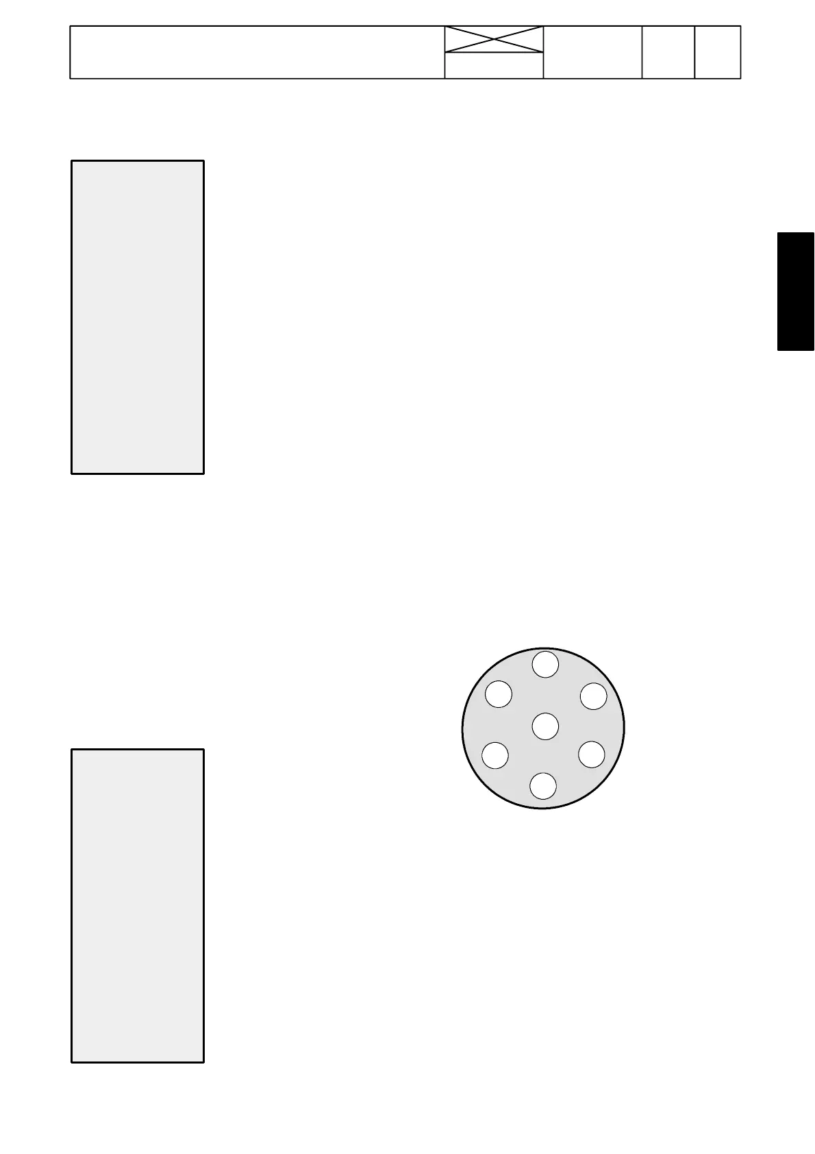
3
4
5
6
1
2
Order of socket poles seen from the rear.
7
Function of pole : Wire colors:
1=RPM sensor, pressure sensor etc. 1=brown no 384
2=Flow meter 2=green no 385
3=Actuator 1, switch (OUTPUT) 3=yellow no 380
4=Wheel sensor, implement sensor 4=red no 388
5=Earthing 5=white GR
6=Supply (battery voltage) 6=black no 17
7=Implement sensor 7=lilac no 383
TESTING OUTPUT:
7. Select test output function (next after test input). Connect
a voltage meter or a test lamp between poles 3 and 6.
Whenyoupressbutton“OUT1”thevoltagemustbeupas
long as you press the button.