364
Model Code Page
34. Autocontrol ---III
8. 11. 1990
6600E, 8100E 341 2
15. 6. 1992
E. Potentiometer on the fuel injection
pump
The potentiometer must be adjusted so that when the accel-
erator pedal (governor control lever) is in its extreme posi-
tions, the pedal (or governor control lever) movement is not
limited by the potentiometer because it does not resist that
kind of load.
Measure the potentiometer voltage between pins 2 and 3 in
connector B8C (under instrument panel). The voltage reading
must be below 3 V when the accelerator pedal is in its upper
position and over 9 V when the pedal is in lowest position. (dif-
ference between max and min reading at least 6 V).
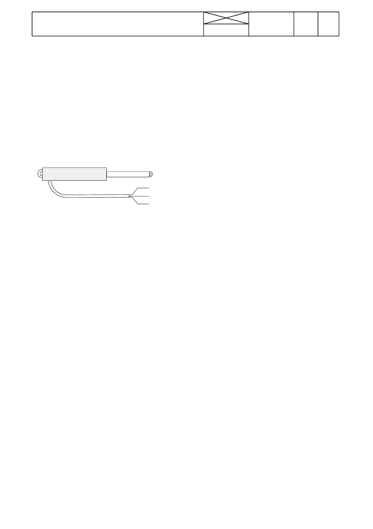
Resistance measurements of the potentiometer:
Black
Red
Yellow
1(+)
2 ( --- )
3(Sign.)
1 --- 2 :
resistance about 1,01 kΩ
3 --- 2
--- spindle in, resistance about 0,62 kΩ
--- spindle out, resistance about 1,89 kΩ
If the resistance values deviate, the potentiometer is faulty.
F. Sensor for engine coolant temperature
Press once the temperature---key and the engine coolanttem-
perature can be seen in the display. Measure the coolant tem-
perature with a separate thermometer and compare the read-
ings. If the display reading is faulty or there is no coolant
temperature reading, check the sensor and its wiring. If these
are OK the ECS or the display unit can be faulty.
Resistance values at certain temperatures:
--- 2 0 ˚C 6480± 1000 Ω
±0˚C 2450±320 Ω
+20˚C 1450±118 Ω
+40˚C 496±44 Ω
+60˚C 245±22 Ω
Pins: Sensor poles
Plug X19/27
Connector X1C/9
ECS connector A2C/30
G. Sensor for outdoor temperature
Press the temperature---key twice and the display will show
the outdoor temperature. Compare the display reading with
a reading measured with a separate thermometer. If the read-
ing is faulty or there is no outdoor temperature reading on AC
III display, check the sensor and its wiring. If these are OK the
ECS or the display unit can be faulty.
Resistance values at certain temperatures:
±0˚C 10,00±1,0 kΩ
+22˚C 3100±50 Ω
Pins: Sensor poles
Plug X19/26
Connector X1C/4
ECS connector A2C/29
H. Sensor for steering angle
A steering angle sensor magnet must be fitted so that yellow
dots point towards the sensor. Distance between the magnets
and sensor must be adjusted to 5 mm. When the front wheels
are straight ahead, the middle magnet should be opposite the
center line of the sensor.
--- sensor resistance is 33 Ω, when the sensor is at the magnet.
--- o t h e r w i s e 10 kΩ or greater
.
Pins: Sensor poles
Plug X19/25
Connector X1C/3
ECS connector A2C/15