63
Model Code Page
21. Engine
1. 9. 1992
6000--8750
213 7
3. Balancer unit, 420---engines
A. Removing and dismantling balancer
unit
1.Removetheengine(Note! The balancer unit can also be
detached when the engine is attached to the tractor. In this
case,removethefrontaxleandtheoilsump,seealsopage
219/1).
2. Disconnect t he lubricating oil pipe of the balanc er unit.
3. Remove the balancer unit. Take care of any shims.
4. Loosen the locking screws and press out the shafts in the
direction of the locking screws. Remove the counterweights
and thrust washers.
5. Clean all parts.
B. Reconditioning balancer unit
Check the shafts, gear wheels and bushings for wear and
damage.
1. If one of the gear wheels is damaged, change both counter
weights as a complete unit. The gear wheels are not available
separately as a spare part.
2. Remove, if necessary, the old bearing bushings with a suit-
able drift. Before removing them, mark the position of the
bushing oil groove on the counter weigh. Press in new bush-
ings in the correct position. After fitting the bushings should
be reamed to a correct dimension, see Specifications.
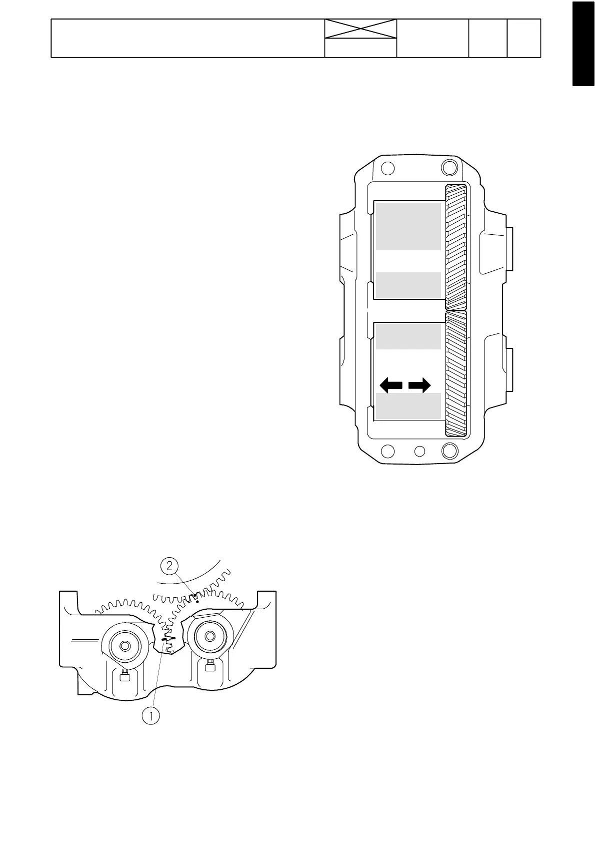
1. Synchronization marking (notch)
2. Marking against crankshaft (punch mark)
4. Place the weights in the body, observing the no tch mark-
ings. The gear wheel with the punch mark runs against the
crankshaft and should therefore be placed highest. Insert the
shafts, remembering the thrust bearings. Apply thread lock
fluid Loctite 270 to the locking screws, and lock the shafts.
0, 1 --- 0, 5 mm
4. Check that the tooth backlash is 0,05---0, 25 mm and that
the end float is 0,1 ---0,5 mm