142
Model Code Page
37. Autocontrol 5 / 5.2
1. 8. 2000
370 24
6250--8950
1. 9. 2002
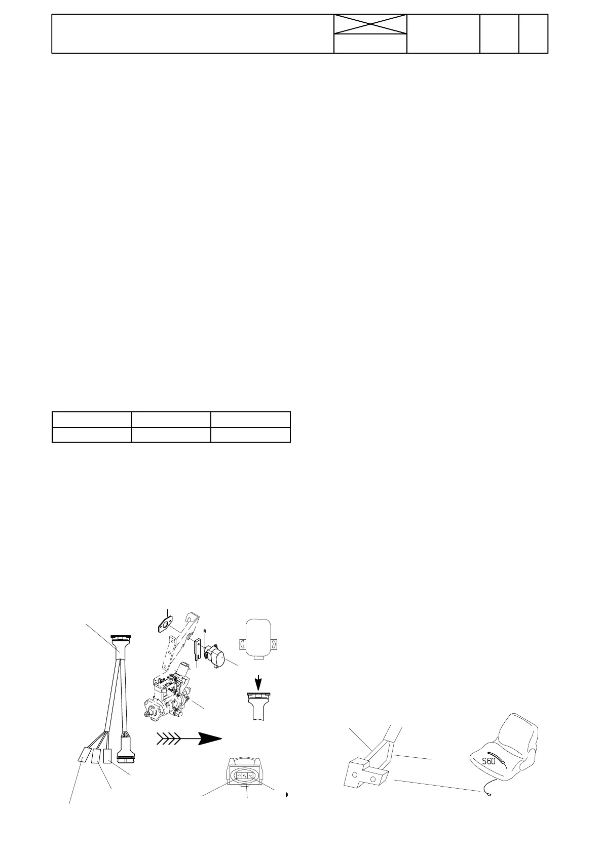
G. Gas pedal (fuel injection pump) posi-
tion sensor B15 in AC 5 (AC 5.2, see page
371/14).
Note! If this s ensor is faulty, there occur malfunctions in the
DPS auto matic speed change (auto1, aut o2). Also a faulty
engine speed sensor can cause this kind of malfunctions.
If the position sensor has malfunctions, the self--- diagnosis
shows the fault code A313.
1. Check in the test mode FII (table b on page 370/11),
whether t he pedal values are between the given limits. If the
function is incorrect, check the position sensor bearings (no
clearance) fitting and wires and wear of the pump pin. Also
check the sensor. Also check the connector X1A (in engine
compartment).
2. Measure, if needed, the position sensor voltages. Check
the voltages always before calibrating the pedal. Connect
ETV 894 100 between the sensor and its connector (see
picture below). If ETV is not available, measure the supply
voltage in the wire loom connector (see pictur e on the next
page). Signal voltage can be measured from control unit A1
connector A1A3/4---A1A3/5 (see page 370/25). The volt-
ages can also be measured in connector X1A.
--- measure the supply voltage (7,7...8,3 V) between pins 1
and 3.
--- measure signal voltage between pins 1 (ground) and 2
(signal). Ensure that the vol tage value changes evenly
when moving the position senso r lever. Adjust the sensor
position if necessary. If the position sensor is faulty, fit a
new one in the correct way (punch mark on shaft towards
lever) and perform the calibration of the pedal. Adjust the
position of the sensor. Fasten the sensor in point, in which
thesensorshaftisinthesamelinewiththepumplever
shaft (see point A in picture below).
Gas pedal
Pedal up Pedal in bottom
Signal voltage 5,7 ---5,8 V 1,5---4,0 V
Adjust the pedal “upper” value and check then that the
pedal “bottom” position value is within the given limits. Se-
cure the screw, which fasten the arm to the sensor spindle
with Loctite 222.
3. P erform the pedal calibration according to instr. B on
page 370/15. If the calibration failed, turn the sensor into a
little different position and try again the calibration. When
needed, try the test with a new senso r.
Only on model 8950 can the sensor be fitted in different
way with fitning set no. 345 60 300 (see fitting instruction
39.25)
Note! Thecalibrationofthegaspedalmustbedoneac-
cording to the periodical maintenance program.
3 Red, +7,7...+8,3 V
2Blue,signal
1Black,earth
ETV 894 100
B15, B16
A
A
1
2
(signal)
3 (+7,7...8,3 V)
A
H. Detection of driver in AC 5 and 5.2
Purpose of the switch S60
InAC5/5.2isusedforsafetyreasonssocalleddriver
detection system. The detection switch prevents uninten-
tional engagement of the PowerShuttle in the situations, in
which the driver does not sit on the seat.
Function
TheswitchinquestionhasbeenconnectedtoAC5/5.2
contr ol unit pin d05. When the driver is sitting on the seat
(weight must be over 30 kg), the switch contacts are
closed and d05 is activated (GND control). The function of
the switch can be seen in table a on page 370/10 (AC 5) or
on page 371/8 (AC 5.2). When the driver leaves the seat,
the switch contacts open (delay 6 seconds. 4 sec. in pro-
gram versions 38, 40, 41 and in AC 5.2 30 sec. if the clutch
pedal is depressed).
Function in different situations
When the driver engages the PowerShuttle direction, the
AC 5 control unit checks the signal from the seat. If there is
not a signal (driver does not sit on the seat) , the direction
arrow in the AC 5 display starts to blink and the direction is
not engaged. After this the direction can be engaged just
when the shuttle lever is moved to the parking brake posi-
tion, the seat signal is activated (driver sits on the seat) and
the direction is re---engaged.
If the direction has been engaged (or is being engaged)
and the seat signal disapperas (e.g. driver stands up from
the seat), a counter is started. The counter damps possible
disturbing information, which can appear e.g. when driving
on an uneven ground. If the seat signal remains floating
(driver does not sit on the seat) over 6 seconds (4 sec. in
program versions 38, 40, 41 and in AC 5.2 30 sec. if the
clutch pedal is depressed), the Shuttle is disengaged and
the direction arrow starts to blink. After this the direction can
be engaged just when the shuttle lever is moved int o the
parking brake position, the seat signal is activated and the
Shuttle direction is engaged again.
Checking function of the sensor
--- in the test mode FII (digital input d05)
--- with ohmmeter in the wire loom connector ( beside the
seat base). The switch is normally open, but closes, when
driver sits on the seat
Changing the sensor
--- remove t he seat upholstery
--- detach the sensor from its holder by pulling it
--- remove the sensor together with wire
--- pass a new sensor wire and press the sensor into its
holder.
--- refit the upholstery. Connect the connector. Check the
function.
Brown
wire
Blue
wire