A
B
B
A
D
A
C
D
Standard instrument
Agrodata--- instrument
Agroline ---instrument
85
Model Code Page
8750, 8950
313 1
1. 10. 1999
31. Σ --- p o w e r s y s t e m
1. 9. 2002
1. Descrip tion
A. General
Engine (634 DS/634DSBIE) on Valtra 8750 and 8950 trac-
torshasasastandardequipmentΣ ---power system
(double output system). Tractor transmission max. output is
160 hp, but max. PTO output is 190 hp (8750) / 200 hp
(8950).
The automatics οftheΣ---power system have been
designed so that the engine output for the tractor trans-
mission never is larger t han 160 hp. The injection pump has
a boost control. Pressure loading from the intake manifold
can be cut with the aid of a solenoid valve. When the PTO
loading is high, the intake manifold pressure affects the
membrane of the boost control unit (solenoid valve ener-
gised), which facilitates movement of the fuel injection
pump control rod to the high output range.
When the PTO loading decreases, the solenoid valve is
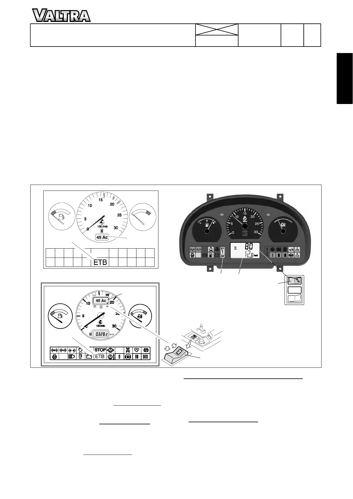
Differences in the dashboard:
On 8750 and 8950 tractors there is a digital instrument (A)
which shows as a percentage, ho w large a part of the trac-
tor total output is transmitted via the PTO unit, when the
PTO is engaged. At other times the Standard instrument
shows tractor running hours.
If tractor is equipped with the Agrodata ---instrument
(see
code 331 page 1),theAc---display mustbeselected in
the upper digital display by using switch (D) (see black
arrow) before the PTO %---display can be seen.
I n L C D --- d i s p l a y o f t h e A g r o l i n e --- i n s t r u m e n t
the upper row
canbechangedbypressingtheRHsideedgeofthe
switch (D), before t he PTO % ---display can be seen. (see
code 333 page 3)
closed (which is controlled fully automatically by the control
unit of the system) and the fuel pump co ntrol rod can move
to the low output range.
The torque of the PTO unit is measured by two sensors.
One sensor is placed at the flywheel under the starter motor
(earlier at the engine front end. On 8950 Hi in front of the
DPS) and another in the PTO unit. These sensors indicate a
twist of the long PTO shaft as a phase shift, which in turn
indicates the torque transmitted by the PTO unit. Always
when the PTO is disengaged, the sensor phase shift is
zeroed automatically to avoid inaccuracies caused by per-
manent deformation of the shaft or phase shift changes
caused by repair works.
The Σ---power system is controlled automatically by the
control unit.
ETB light
(B) Standard and Agrodata ---instruments.
When the higher output range of the engine is engaged,
there is a light ETB in the warning light panel (ETB=Extra
Turbo Booster). The ETB --- light has also a fault diagnostic
function. It indicates by flashing, if the system has malfunc-
tions.
Σ light
(C) Agroline---instrument.
When the higher output range of the engine is engaged,
there is a light Σ in the warning light panel. The Σ --- l i g h t h a s
also a fault diagnostic functio n. It indicates by flashing, if
the system has malfunctions.
Note! If an electric welding is done on the tractor or on the
trailer or implement, which are attached to the tractor, both
battery cables must be disconnected. Otherwise the
Σ---Power system may be damaged.