313
Model Code Page
32. ACB power lift
1. 11. 1998
8250--8150
321 8A
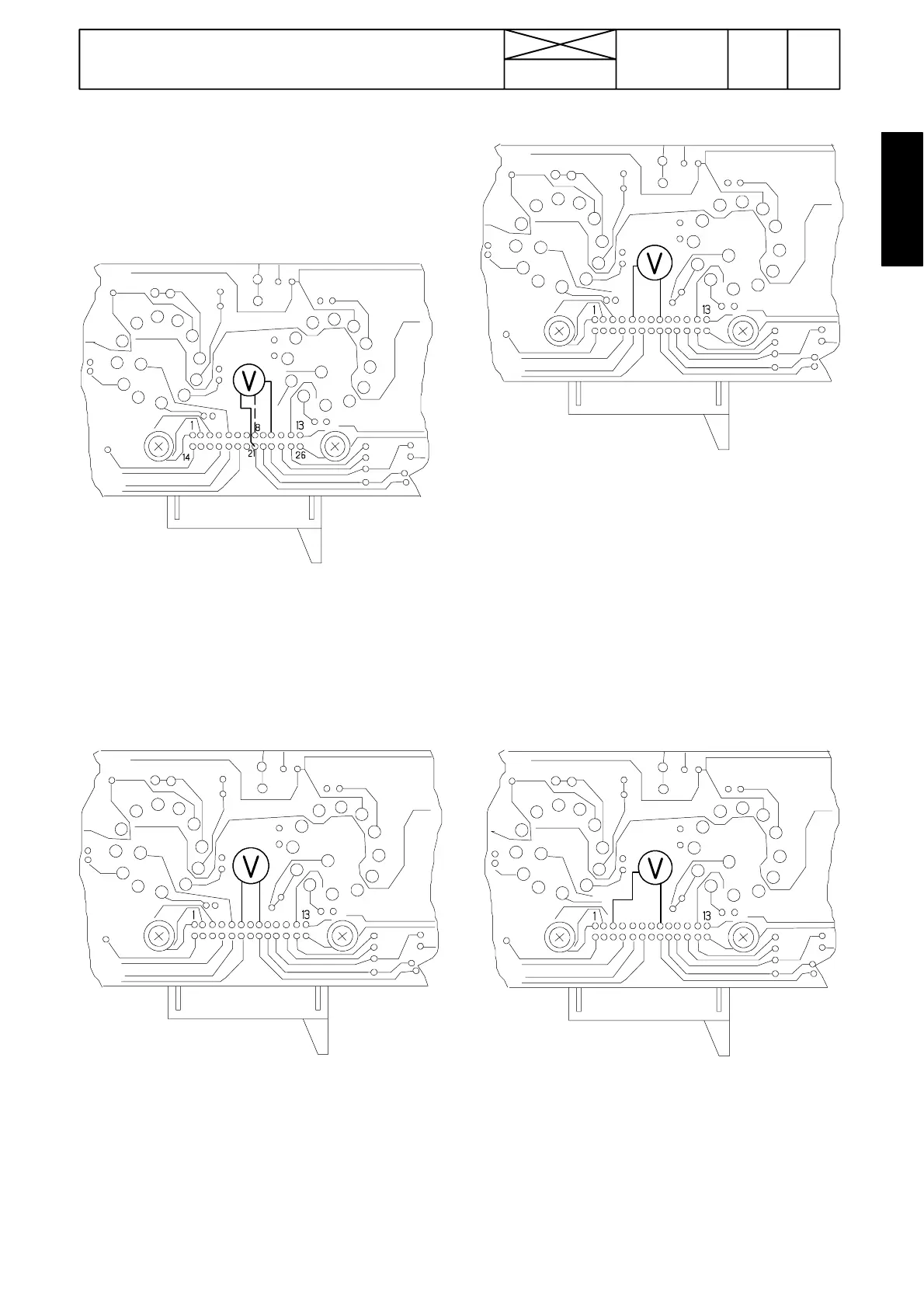
F.2. Checking switch panel of ACB
Remove the switch panel from the lever console (do not dis-
connect the connector). Switch on currrent and activate the
ACB power lift. Measure from the terminals on the rear side of
the circuit card (DC).
1. Measuring supply voltage
Picture a) Measure supply voltage between pins 21 ( --- )
and 10 (+): Correct value is 9,2 ---9,8 V (DC). Measure also
voltage between pins 21 and 8. Correct value is about 1,6
V.
Note! If the supply voltage is incorrect, the fault lies in con-
nectors/wires.
2. Checking lowering speed selector S7E
Picture b) Measure voltage between pins 8 and 6 with all
selector positions:
Position Pin 6
1 0 , 3 --- 0 , 5 V
2 0 , 7 --- 1 , 1 V
3 1 , 1 --- 1 , 5 V
4 1 , 6 --- 2 , 0 V
5 2 , 3 --- 2 , 9 V
6 3 , 1 --- 3 , 7 V
7 4 , 1 --- 4 , 7 V
8 5 , 6 --- 6 , 0 V
9 7 , 6 --- 8 , 2 V
3. Checking transport height selector S8E
Picture c) Measure voltage between pins 8 and 5 with all
selector positions:
Position Pin 5
10
2 0 , 9 --- 1 , 2 V
3 1 , 9 --- 2 , 3 V
4 2 , 9 --- 3 , 3 V
5 3 , 9 --- 4 , 3 V
6 4 , 9 --- 5 , 4 V
7 5 , 9 --- 6 , 4 V
8 6 , 8 --- 7 , 5 V
9 7 , 6 --- 8 , 2 V
4. Draft control selector S9E
Picture d) Measure voltage between pins 8 and 3 with all
selector positions:
Position Pin 3
P 7 , 6 --- 8 , 2 V
1 4 , 0 --- 4 , 4 V
2 3 , 3 --- 3 , 6 V
3 2 , 4 --- 2 , 9 V
4 1 , 6 --- 2 , 6 V
5 0 , 7 --- 1 , 0 V
60