65
Model Code Page
21. Engine
1. 8. 2000
6000--8950 214 1
1. 1. 1994
Timing gears (Op no 214)
A. Removing timing gear casing
As the timing gear casing forms a seal against the oil sump,
the casing cannot be removed without first removing the
frontaxleandtheoilsump(seepage219/1 for working
order).
1. Detach the engine (or the oil sump).
2. Remove the cooling radiator, alternator and the fan belt
(if not removed earlier).
9101 65700
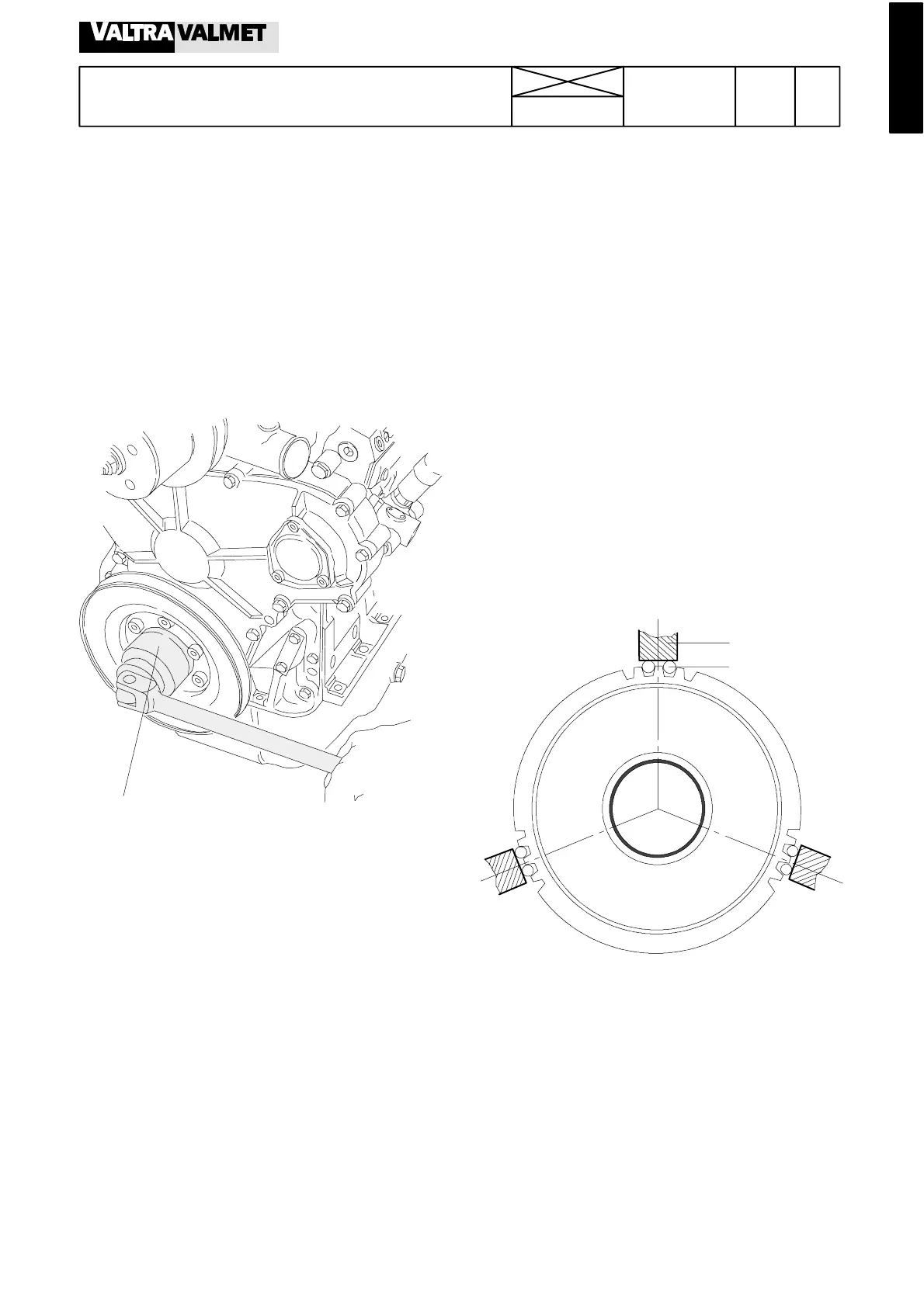
3. Loosen the crankshaft nut (special tool 9101 65700 for
320, 420, 620 engines and tool 9024 55800 for 634
engines) and remove the bel t pulley/hub.
Note! Warm the nut with a hot---air blower before unscrew-
ing (locking fluid. Do not damage the seal). The thread is
normal RH thread. Support the key so that it cannot slip
(600 Nm/1000 Nm). Rotation of the crank shaft can be pre-
vented by fastening a support on the hub (remove the belt
pulley and fasten the support to the hub) or you can use
an air po wered nut opener, and the crankshaft does no t
rotate . When needed, the hub is removed with an extract or.
Note! On 620---engines the belt pulley must be removed
before unscrewing the nut.
4. Remove the timing gear casing cover and the oil deflec-
tor ring at the front end of the crankshaft.
5. Remove the injection pump.
Note! If the timing gear casing is not to be changed, the
injection pump can remain in place. In which case disco n-
nect all leads and pipes from the pump.
6. Unscrew the idler gear bol ts (17 and 22 mm). Remove the
flange, gear wheel and bearing journal.
7. Extract the camshaft.
Note! If the cylinder head and valve mechanism have not
been removed, the tappets must be prevented from falling
down, see Op. 212 2B.
8. Remove the timing gear casing (13 mm). Ensure that all
sealing surfaces are not damaged.
9. Remove the crankshaft front sealing ring from the front cas-
ing and clean all the parts that have been removed.
B. Reconditioning i dle r gear
If the idler gear bushing is changed, press in a new bushing
so that its rear edge is 0,1 ---0,25 mm inside the gear wheel
rear edge (see picture on next page).
1
2
1. Chuck of lathe
2. Roller ø=5 mm
Machine the idler gear bushing inner diameter to a correct
dimension after fitting. Centre the idler gear according t o fig-
ure above so t hat tooth backlash is kept the same.