326
Model Code Page
33. Valmet Agrodata
8. 11. 1990
6000--8400 330 2
5mm
1
2
3
4
6
5
(F17)
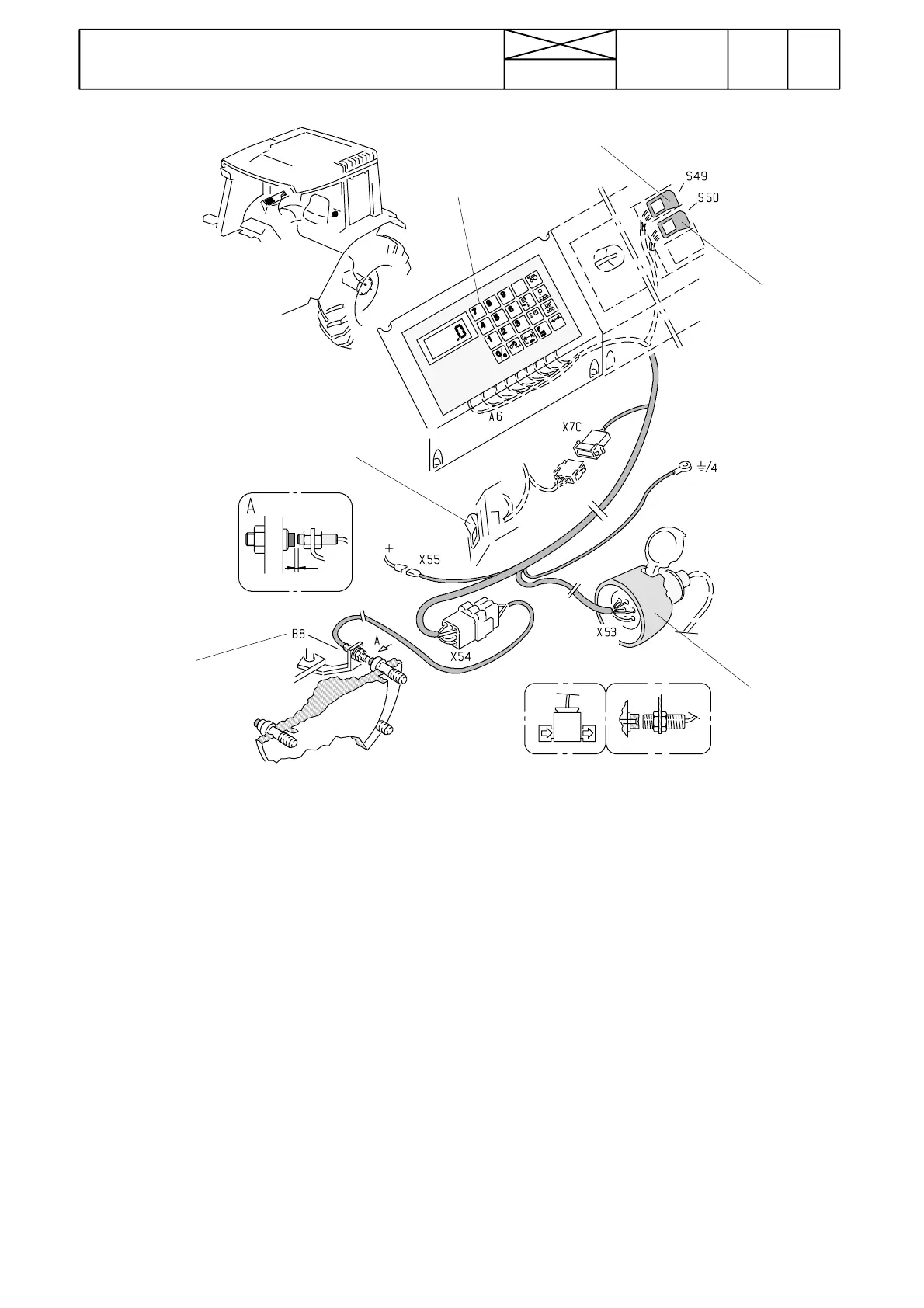
Fig. 2. Agrodata monitor and sensors
1. Agrodata unit
2. Magnetic sensor for detecting wheel rotation speed
3. Socket for connecting sensors on implement
4. Lift/lower switch for power lift (stops the area meter when
the implement is raised)
5. Selector switch; selects between tractor and implement
wheel sensor for measurement of speed and area
6. Selector switch; selects between measurement of engine
revs and measurement of implement functions (Eg. piece
counter or flow rate)
Equipment
The Agrodata unit consists of a monitor in the cab, wheel sen-
sor (engine RPM sensor not fitted), socket for connecting sen-
sors on implement, leads connecting monitor and sensors
and supply voltage leads.
The Agrodata unit fuse (F17, 10 A) is placed in the fuse box.
The connectors are placed in the lever console in the cab. The
connectors are accessible by removing the side panel of the
console.
On the rear cover of the Agrodata unit there are terminals for
sensor leads and supply voltage leads. The terminals are
numbered from one to nine. The leads have corresponding
numbers (to terminal 9 is connected lead no 19)
X55=supply voltage connector
X54=connector for sensors and implement socket
B8=wheel sensor
X7C=connector to lift/lower switch of power lift
X53=socket for sensors on implement
S49=selector switch
S50=selector switch
A6=Agrodata unit
The Agrodata system uses magnetic sensors. When the
magnet and the sensor are in close proximity the sensor is
activated and an electrical signal is transmitted to the monitor
display.
The wheel sensor is fitted on the LH rear wheel mounting
flange. Several magnets can be fitted on the wheel, evenly
spaced for more accurate measurement of driving speed.
Correct speed measurement is not possible if too few
magnets are used with a big wheel.
Agrodata is connected to the hydraulic power lift. When im-
plement is raised with the lift/lower switch, the area meter is
stopped.
Sensors on implement (Eg. flow meter, piece counter etc) can
be connected to the Agrodata via the socket at the rear of the
tractor (implement sensors must be ordered separately from
the factory).