269
Model Code Page
31. Σ --- p o w e r s y s t e m
1. 10. 1999
8750 313 11
1. 8. 1998
3. Start the engine and let it run about 20 s at the low idling
speed, PTO disengaged and the hydraulic pump in unload-
ing circuit. Now the Ac ---display must show 0, then the
control unit has made the calibration of the zero --- mode.
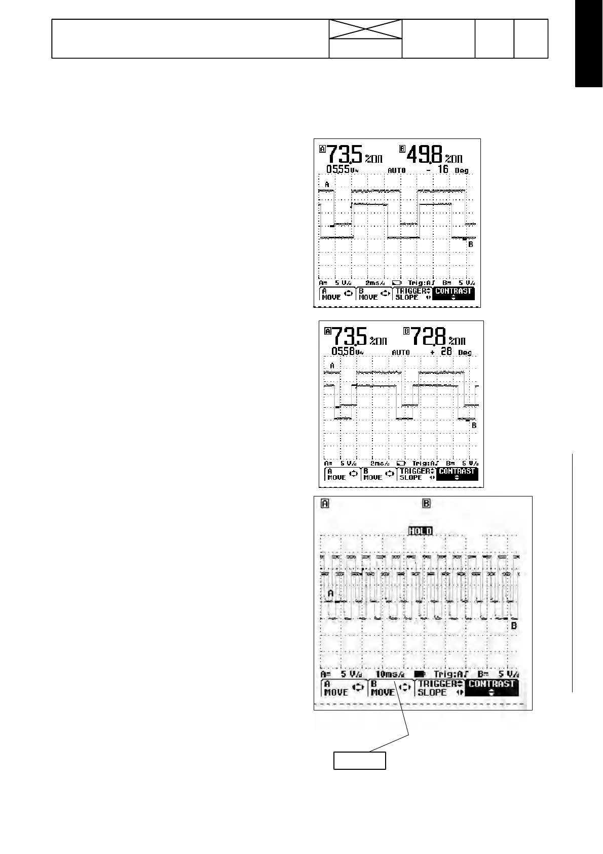
4. In the Fluke -instrument display there must appear two
step waves (see picture). The upper A ---wave shows signal
fromtheenginesensorB4andthelowerwavesignalfrom
the PTO sensor B5.
If one of the waves does not appear, check the wires and
measure internal voltages. Change the sensor(s) when
necessary. Adjust the distance between the sensor and the
impulse wheel to 0,8 mm. Turn the sensor fully home (not
at the notch), after which open it 1/2---2/3 turn (thread
M18x1,5), the clearance is then 0,75---1,1 mm (locking nut;
spanner width 27 mm). If the front sensor impulse wheel is
located at the front end of the crankshaft (--- H02430), the
clearance is easy to adjust to 0,8 mm.
5. Let the engine run at the low idling speed and read off
the pulse ratio values (% D). Raise the revs evenly to the
max.revsandreadagainoffthepulseratiovalues.The
values are allowed to change at the most 5% ---units. The
readings can be between 40---75% (PTO type and position
oftheforemostsensoraffectthereading).Thechangeof
the pulse ratio values at different engine revs must be within
the permissible %---limits.
If necessary, unscrew the sensor locking nut and adjust the
sensor distance from the impulse wheel by turning the sen-
sor a little at a time and by waiting for a while to show influ-
ence of the adjustment, until the readings remain within the
given limits in the whole engine revolution range. Be care-
ful not to touch the impulse wheel with the sensor: sensor
can be damaged. The sensor end must always be at least
0,7 mm out of the impulse wheel surface (at least 1/2 turn
open).
6. Read off sensors’ phase difference, the change can be
at the most 10˚ between the min and max revs of the
engine. The value of the phase difference is unimportant,
only the change is important (the phase difference value
can be any between 1..180 ( o r - 1 --- 1 8 0 ). If the value is
e.g. 175 at the low idling speed and at max. revs ---8
the change is 13 ˚.
7. Set the display time value to 10 ms/d (with time---key).
Let the engine run at low idling speed. Check that waves
areinthedisplayinevendistancesandthatnowaveis
missing (stop the waves with hold---key).
8. Set the display scale to 5 ms/d, raise the engine revs to
2100 RPM. Check the same values as in stage 7. If one
wave is missing, adjust the sensor and test its function.
9. Carry out the same test as in instr. B in paragrapf 4. If it is
possible to use a PTO brake, the ETB light must come on
with readings 25..32 % in the Ac---display (ca. 350---450 Nm
in the PTO shaft). When loading the PTO the B---wave (sen-
sor B5) is moving to the right and the phase difference
value must change.
If still malfunctions occur, change the control unit A13.
10. Disconnect the measuring cable and wires from the
tractor, and connect connector A13. Ensure, that the sensor
locking nuts are tightened.
Figures below show two different measuring results from
two different tractors with different PTO units (widths of
waves). The position of the waves depends on a tractor,
and thus the oscilloscope reading varies in different trac-
tors.
EXAMPLE 1. PTO 1000/750 (540E)
EXAMPLE 2. PTO 1000
sTIMEns
+ ---
10 ms/d 800---900 rpm
5 ms/d 2100---2200 rpm
51,7 %Dτ
ττ
τ
54,9 %Dτ
ττ
τ
05,55 V~
--- 1 0 5 D e g