1005
Model Code Page
66. Air suspension of front axle
1. 8. 2000
660 36200--8950
1. 11. 1998
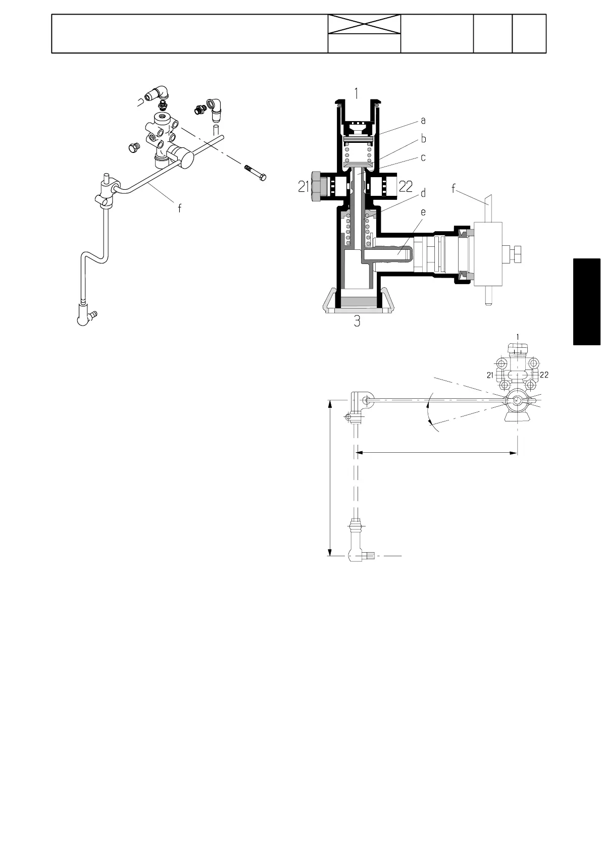
1. L evelling valve
A. Function
When the loading on the front axle increases, the tractor
frame/levelling valve moves downwards. Linkage lifts up
the link ( f) and sleeve (d) with the aid of the cam pin (e).
When the sleeve (d) moves upwards, it opens the valve
(b), and compressed air flows from the reservoir through
port (1) and valve (a) into the suspension rubber bellows,
which are connected to port 22 (port 21 is plugged).
When pressure increases in the bellows, t he frame moves
upwards, and link (f), when moving downwards, closes the
valve (b).
When pressure increases in the bellows and link (f)
together with the cam pin ( e) move downwards, excess air
from the bellows can flow through passage (c) and hole (3)
to atmosphere. Now the tractor frame moves downwards
and link (f) returns into the normal horizontal position. When
passage (c) is closed, the levelling valve is again in the
balanced position.
B. Adjustment
--- lower the tractor frame into the lowest position against
the limiter
--- fill the bellows slowly. The valve must stop the lifting
movement, when the locking pin holes align in the front
part of the suspensio n frame. If the tractor rises more,
lower the tractor frame and make the vertical link longer.
--- check the adjustment again and change the vertical link
length until the l ifting height is correct (locking pins holes
align).
--- if the closing angle (l i nk near horizontal) is reached
before the correct height, shorten the vertical link.
L = 150 (Valtra tractors)
Amin = 150
α
Note! The total stroke of the bellows on V altra---tractors is
± 72 mm i.e. H= 144 mm ( front wheel suspension is then
±40 mm).
Note! Separate spare parts are not available for the valve.
In case of a damage a new valve must be fitted. When fit-
ting a new valve, the adjusting values can be set into the
same values as for the old valve ( however, the adjustment
must be checked).