The fuel feed pump draws fuel from the tank via the water trap
and the filter into the fuel injection pump.
In the pump fuel flows through the inlet filter screen into the
vane type fuel transfer pump. Some fuel is bypassed through
the pressure regulator assembly to the suction side.
Fuel under transfer pump pressure (1---6 bar) flows through
the center of the transfer pump into the circular groove on the
rotor. It then flows through a connecting passage in the head
to the automatic advance and up through a radial passage
and then through a connecting passage to the metering
valve. The metering valve adjusts amount of injectedfuel and
position of the metering valve is controlled by the governor
(revolution lever) and the stop solenoid. From the metering
valve fuel flows to the radial charging passage and further to
the head charging ports.
As the rotor revolves, the two rotor inlet passages register
with the charging ports in the hydraulic head, allowing fuel to
flow into the pumping chamber. With furtherrotatio n, the inlet
passages close and the port to the injectors opens.
Function
While the discharge post is opened, the rollers contact the
cam lobes forcing the plungers together. Fuel trapped
between the plungers is then pressurised and delivered by
thenozzletothecombustionchamber.
The injection pump is self---lubricating, and it has not been
connected to the engine lubricat i on system.
As fuel at transfer pump pressurereachesthe charging ports,
slots on the rotor shank allow fuel and any entrapped air to
flow into the pump housing cavity. In addition, an air vent
passage in the hydraulic head connects the outlet side of the
transfer pump with the pump housing. This allows air and
some fuel to be bled back to the fuel tank via the overflow
valve.
The fuel thus bypassed fills the housing, lubricates the inter-
nal components, cools and carries off any small air bubbles.
The pump operates with the housing completely full of fuel;
there are no dead air spac es anywhere within t he pump.
103
Model Code Page
22. Fuel system
15. 5. 1996
8050--8550 220 13
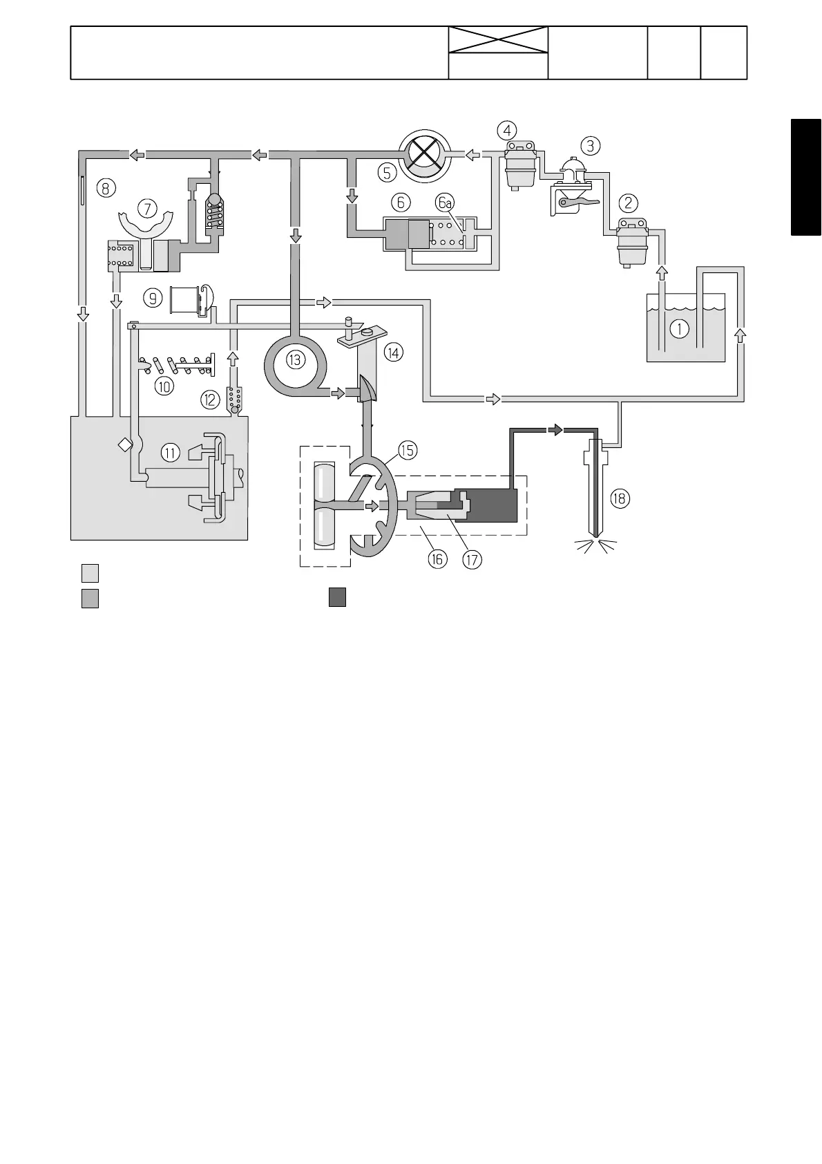
Stanadyne distributor pump
Transfer pump pressure Injection pressure
Housing pressure
1. Fuel tank 10. Regulator spring
2. Water trap 11. Centrifugal weights
3. Fuel feed pump 12. Overflow valve
4. Fuel filter 13. Hydraulic head connecting passage
5. Transfer pump 14. Metering valve
6. Pressure regulator valve 15. Hydraulic head charging pasage
7. Automatic advance 16. Distributor rotor
8. Air vent passage 17. Delivery valve
9. Stop solenoid 18. Injector