1186
89.2
Model
No Page
AIR CONDITIONING, FIT TING INSTRUCTION
(PT94--- cabin) 30.07.1999
16(28)
28.06.1999
6000---8750
6250Hi---8950Hi
Temperature:
--- Temperature measurement is carried out in sha-
dow, every ventilation nozzles open, doors a nd
windows closed and after the air conditioner has
been in function 5---10 minutes. Temperature in
the nozzle on the roof console should be a bout
+6...+10 ˚C (at engine revs 1500 r/min, with
max cooling effect, with fan speed II and at out-
door temperature of +20---30˚C).
(Check that the cab heater water valve closes
the circulation of warm engine coolant).
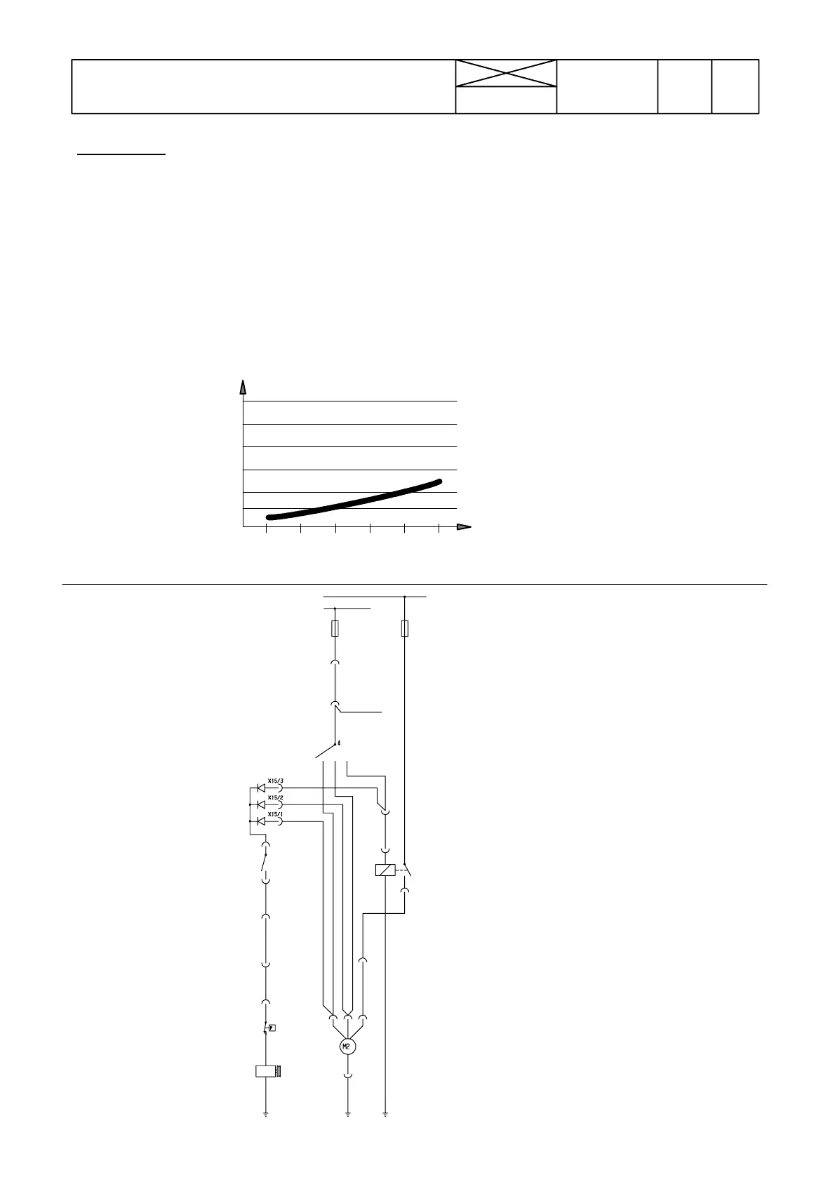
KYTKENTÄKAAVIO
KOPPLINGSSCHEMA
S3
K6
S8
S19
Y5
M2
X15
234
1
1023
S 3 Kytkin, puhallin
S 8 Kytkin, ilmastointilaite
S19 Kytkin, kompressorin paine
M 2 Puhallin
X15 Liitinkotelo, 3---os., ilmastointil., diodit
Y 5 Magneettiventtiili, kompressori
K 6 Rele, puhallin III---nopeus
Strömställare, fläkt
Strömställare, luftkonditionering
Luft kond, tryckvakt
Fläkt
Relä, fläkt III---hastighet
Kopplingsbox, 3 poler, luftkond, dioder
Magnetventil, kompressor strömuttag
30
15
18KE
F21
F15
18KE
4VI
3RU
38LI
X5/1
38LI
X24/6
38LI
X24/4
18KE
X7/3
70MU
X7/1
X24/5
70MU
X11/9
X19/8
93MU
93MU93MU
2
1
F21 Ilmastointilaitteen sulake
F15 Puhaltimen sulake
Säkring för klimatanl äggning
Säkring för fläkt
Ulkolämpötila ° C
Utetemperatur ° C
Lämpötila, ° C
vasen etusuutin
Temperatur ˚Ci
vänstra främremuns-
tycket
Lämpötilaero vas./oik. etusuutin
max. 3
˚C
Temperaturskillnad mellan vänstra
och högra ventilationsmunstycken är
max 3˚ C.
Temp difference between left and
right front nozzles is max 3˚C.
Temp. ° C
left front nozzle
Outdoor temp.° C
Fan switch
Switch, air conditioner
Pressure switch
Fan
Relay, fan speed III
Air conditioner fuse
Fuse for fan
Connector, 3 pins, air cond., diodes
Compressor magnetic clutch
WIRING DIAGRAM
20 22 24 26 28
12
14
16
18
20
30
10