27
Model Code Page
22. Fuel system
1. 9. 2002
6200--8550 223
13
1. 11. 1998
I. Dynamic adjustment of injection
timing
1. Let the engine run to a normal working temperature before
adjustment.
Note! Stop the engine before connecting and disconnecting
the adjusting device.
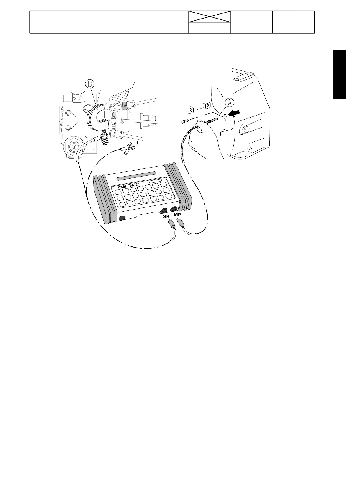
2. Remove the protective plug on the fly wheel housing on the
LH side of the engine and fit the magnetic sensor A into the
8 mm hole. Press the sensor against the fly wheel . The sensor
must not touch the fly wheel so pull it a little out (0,5...1,0 mm)
. Connect the sensor connector to the test device plug MP.
3. Fit fastener B on the brass ring between the pump and pipe
and tighten the screw. Ensure, that the screw end touches the
brass ring. Connect the injection sensor connector to the test
device plug SR. Connect th earth wire to the clean metal sur-
faceontheengineorfuelsystem.
4. Switch on the test device by pushing ON/CLEAR button.
In the display is visible ”Time Trac” and ”Model TT 1000” and
then i ”R= 0”. Now the device can be used as a rpm counter
without other procedures.
5. Press button MAG PROBE. In the display appears ”Trig
Level 30%”. Confirm by pushing ENTER.
6. In the display is visible ”Offset 20.0˚ ”. Confirm by pushing
ENTER.
7. In the display is visibl e ”Calibrate?” . Start the engine and
let it run at low idling. Press ENTER so that in the display is vis-
ible ”R=Set RPM”. Compare the revs on the dashboard rev
counter reading and specified values with TimeTrac, see
pages 210/3, 210/18 and 210/19.
Note! Ensure before engine start that the wires do not to-
uch the exhaust manifold or movable parts.
8. If the revolution reading is correct, press ENTER after
which text ”Calibrating...”. is visible in the display
Note! If the revs signal disapperas or engine stops , in the
display flashes text ”Eng. Not running” and the device re-
turns to the revs mode. Start again by pressing button
MAG PROBE (return to point 5).
9. If the engine is running at 850 r/min and the pump ad-
vance is 6˚ btdc, in the display there is visible ”R=850 MP
+ 6.0”. Now the device is ready for adjustment.
Note! If the magnetic sensor signal is cut or the sensor is
lacking, in the display there is text ”R=850 No Probe”.
When the signal returns, the device shows again the injecti-
on advance.
10. The injection time is checked at high idling revs [TT
(HI)]. If the injection timing deviates much from the speci-
fied value, adjust the base timing of the pump or check
possible disturbances.
If the values of the dynamic timing cannot be adjusted to
specified value, then the pump must be repaired in the au-
thorised Stanadyne workshop. The function of the pump in-
jection advance governor is assured by checking the injec-
tion timing at a low idling speed [TT (LI)].
Adjusting values, see tables on pages 220/14.
See also instructions of the device manufacturer.