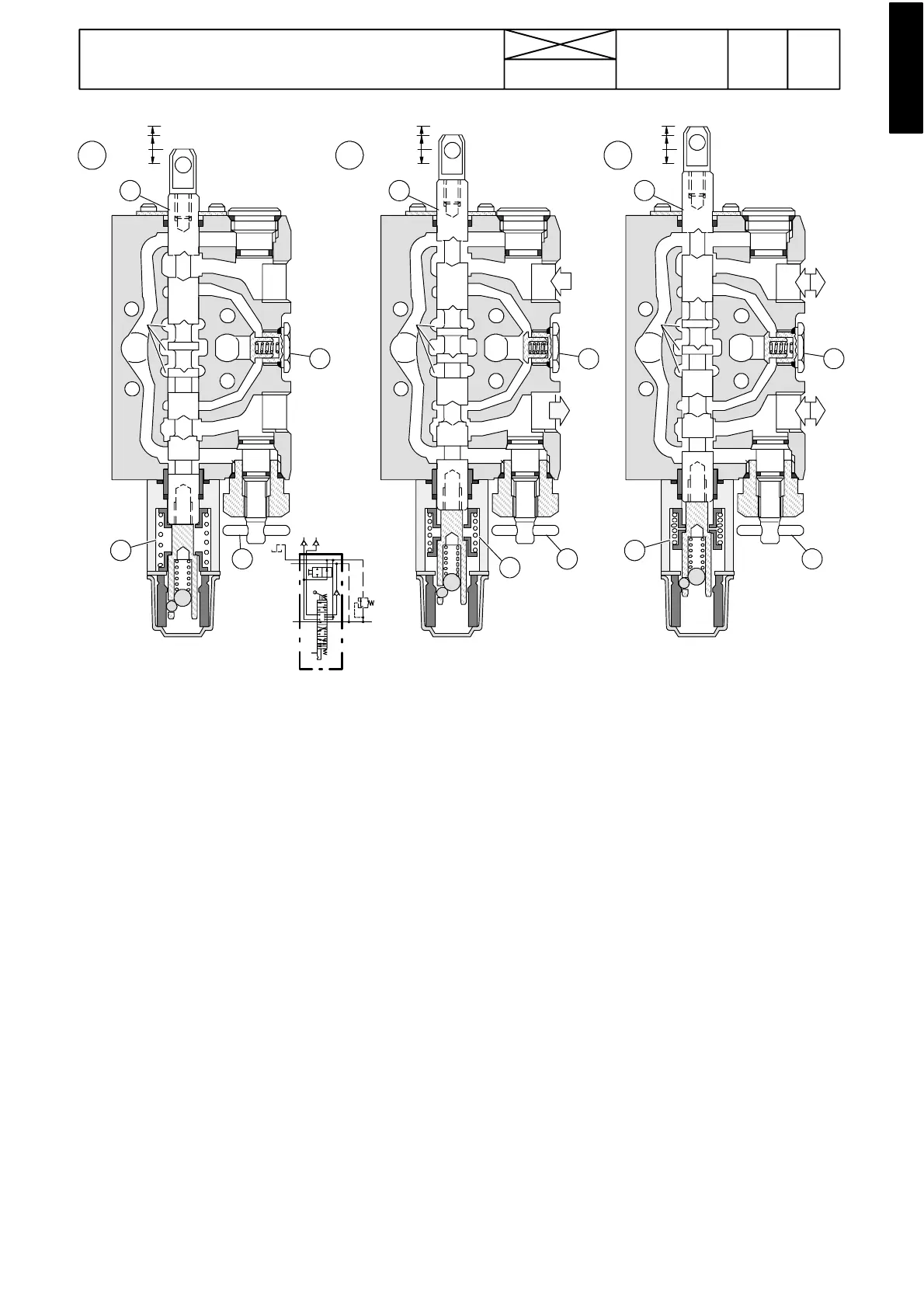
Figure 20. Rearmost standard valve
1233
Model Code Page
90. Hydraulic system
8. 11. 1990
6000--8750 910 21
A BC
N
1
A
B
P
3
2
4
T
N
N
1
A
B
P
3
2
4
T
N
N
1
A
B
P
3
2
4
T
N
P
P
T
19 MPa
--- The rearmost standard valve (order no. 32536500): 1/2
--- a cti o n, 4 p o s i ti on s (ou t --- h o l d --- i n --- f l oa t ) , sp r in g --- r et u rn .
Floating position can be locked.
Function:
A: Neutral position. Oil flows from the priority valve (and valve
no 1) through the flow---through channels N to the control
valve of the hydraulic lift. The channels to the auxiliary hy-
draulics (A, B) and the non---return valve 2 are closed.
B: Pressure position: When the slide 1 has been moved up-
wards, the middle part of the slide closes the channels N,and
its lower part opens the line to the port B. Pressure in the chan-
nel N and in channel P increases (these channels unite in the
front end flange).
The non---return valve 2 opens and oilflowsto the auxiliary hy-
draulics via port B. At the same time the slide opens the return
line from port A to tank channel T.
When the slide has been moved downwards, the port A is
pressurised and return oil flows via port B.
C: Floating position: The slide 1 has been moved further up-
wards. The detent balls lock the sleeve. The sleeve opens the
middle channels N and oil flows to the hydraulic lift.
Thelinesfromthepressurechannel P to ports A and B are
closed. Both ports A, B are connected to tank channel (and
to each other).
--- T h e ch a n g e --- o v e r v a lv e 4 is used to give a double---acting
valve a s ingle---action function. When single---acting, the
equipment hose must be connected to the upper connector
A.
1) Slide
2) Non---return valve
3) Centring springs
4) C h a n g e --- o v e r v a lv e