Oil flow control valve
1235
Model Code Page
90. Hydraulic system
8. 11. 1990
6000--8750 910 23
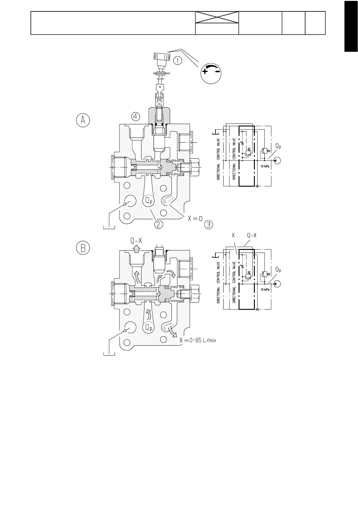
A) The oil flow is not adjusted.
The first spool valve can not be used when the throttle is clo-
sed.The pump flow goesthrough the channel Qp to the spool
valves after the intermediate plate, and further through the po-
wer lift control valve into the tank.
Direction of the pressure to one spool valve or to the power lift.
B) The oil flow is adjusted (and the manual control valve
is in the active position).
The pump flow is divided in proportion to the throttle between
0 and 65 litresper minuteamong thechannelsQ---Xand Xand
can simultaneously be use d for controlling t he spool valve X
(between the pump end plate and the intermediate plate) and
one of the next spool valves, or the spool valve X and the po-
wer lift.
When the throttle spindle 1 is opened, the flow X grows and
the flow Q---X decreases.
If the pressure in channel X varies, the same pressure change
is transmitted through the throttle and the balance piston bore
also to the opposite head of the piston, and this means in
practice that the spindle keeps its position and the flow does
not change.
The throttle in the piston bore prevents vibration.
--- When the oil flow is adjusted, the pressure of the flow X is
the pump pressure minus the spring load. The pressure of the
flow Q---P varies from free flow pressure to maximum pressu-
re, depending on the use of the other manual control valves
/ofthepowerlift.
1) Adjusting knob
2) Pressure channel that goes through the valve blocks
3) Adjusted flow to the X spool valve
4) Surplus flow to other spool valves