261
Model Code Page
31. Σ --- p o w e r s y s t e m
1. 8. 2000
8750 313 5
1. 10. 1999
2. Electric connections, versions 1.0, 1.1 and 2.0
Ac
G22507---
---G22506
*)
*)
*)
*) 8750 with has ver-
sions 1.0 or 1.1: These
wires must be discon-
nected from connector
A13 on the tractor wire
loom side, if version 2.0
contr ol unit is fitted (if
not disconnected
earlier)
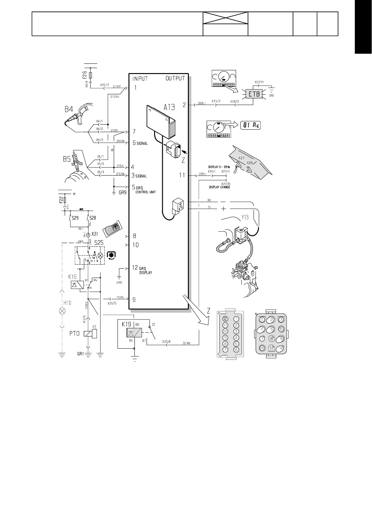
Picture 3. INPUT and OUTPUT signals to/from control unit A13 in versions 1.0, 1.1 and 2.0.
INPUT SIGNALS
Pin 1: Supply voltage (battery voltage) into the control unit A13 and into the sensors B 4 and B5 via fuse F26 and starter
switch.
Pin 3: Signal from the rearmost sensor B5
Pin 4: Earthing of the r ear most sensor B5 (not used in versio n 2.0, wire 215 Green is not connec ted to unit)
Pin 5: Control unit earthing
Pin 6: Signal from the foremost sensor B4
Pin 7: Earthing o f the foremost sensor B4 (in version 2.0 RS232 RxD, wire 213 Gr een is not connected to unit)
Pin 8: Not in use
Pin 9: Control of PTO and %---display. Supply voltage, when PTO is engaged, otherwise 0 V.
Pin 10: Not in use
Pin 12: Earthing of dis play (in version 2.0 RS232 TxD, wire GR9 not connected to pin 12)
OUTPUT SIGNALS
Pin 2: Control of ETB ---light. >10 V, when the higher output range is engaged (in %---display >25---30 %), otherwise 0 V.
Pin 11: Control of %---display. When the PTO is engaged: µ 9V=0%,µ 1V=99%.
Others! Supply volt age (12 V) into the solenoid valve Y13, when the higher output range is switched on (ETB---light il lumi-
nates), otherwise 0 V. Earth from relay K19 into the %--- display, when the PTO is engaged. When not engaged, the digital
instrument shows running hours. Relay K19 changes the display from running hours into the output percentage display.
AD ---instrument shows 0 Ac, although the PTO is disengaged.