278
Model Code Page
31. Autocontrol 2.2 / 2.3
1. 8. 2000
6000--8750 314 6
1. 6. 1999
D. 4WD control
Checking function (engine is run-
ning)
:
--- Depress the 4WD rocker switch rear edge,
at which time the 4WD pilot light must light
up.
This shows that:
--- th e 4WD switch functi ons
--- the 4WD pilot light functions
--- Depressd the switch front edge, at which ti-
methepilotlightmustgoout
--- Depress separately unlatched brake
pedals. The 4WD ind. light must not come
on.
--- Connect the brake pedals together and
depress the pedals at which time the 4WD
engages (ind. light comes on)
--- Release the brake pedals and the ind. light
goes out.
--- apply parking brake, the 4WD ind. light
must come on
--- release parking brake at which time the
4WD ind. light must go out
This shows that:
--- brake pedal switches function
--- relays K7 and K15 function
--- parking brake switch functions
--- Drive the tractor at speed of 4 km/h.
--- M a k e a t i g h t t u r n
--- Engage and disengage the 4WD several
times. When the 4WD is engaged, you
should see the front axle skid and feel a jerk
as you engage and disengage.
This shows that:
--- solenoid valve functions
--- 4WD clutch functions
--- Turn the 4WD switch to the middle position (automatic
position, in which the 4WD engages, when the diff. lock
is engaged). Testing of this position is made in connecti-
on with checking of the diff. lock, see page 314/8 (AC
2.2) or page 314/10 (AC 2.3).
Note! In case of malfunctions always check fuse F22.
When the 4WD is disengaged, the solenoid valve Y3 is
energised and the nut at the end of the valve is mag-
netic which can be verified e.g. with a screwdriver.
Note! 4WD is always engaged, when the engine is stop-
ped (cup springs engage the 4WD). The use of the par-
king brake earths relays K7 and K15 and the 4WD is
engaged.
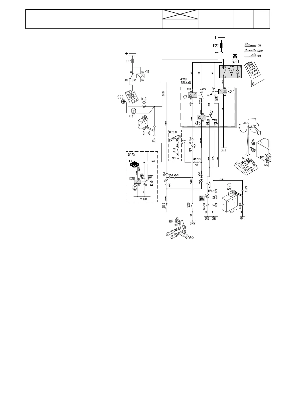
Picture 2.4WD control. The system gets the supply via
the ignition switch and fuse F22.
F22: fuse
S30: three ---position rocker switch of 4WD
Y3: 4WD solenoid valve
H9: 4WD pilot light of 4WD
S10 and S20: brake light switches
K7 and K15: relays, which switch on 4WD, when latched to -
gether brake pedals are depressed.
K27: 4WD relay (4WD engages, when the diff. lock is enga-
ged).
GR1: earth point (solenoid valvest) in the rear part of the lever
console
GR5: earth point under the dashboard on the cab front wall
V1: Solenoid valve diodes (see picture on page 310/6C)
V3: 4WD diode housing (see picture on page 310/6C). This
diode housing is for solenoid valves in AC 2.3.
Note! Engagement of the 4WD during braking can be preven-
ted, when relay K7 (in the fuse box) is removed.