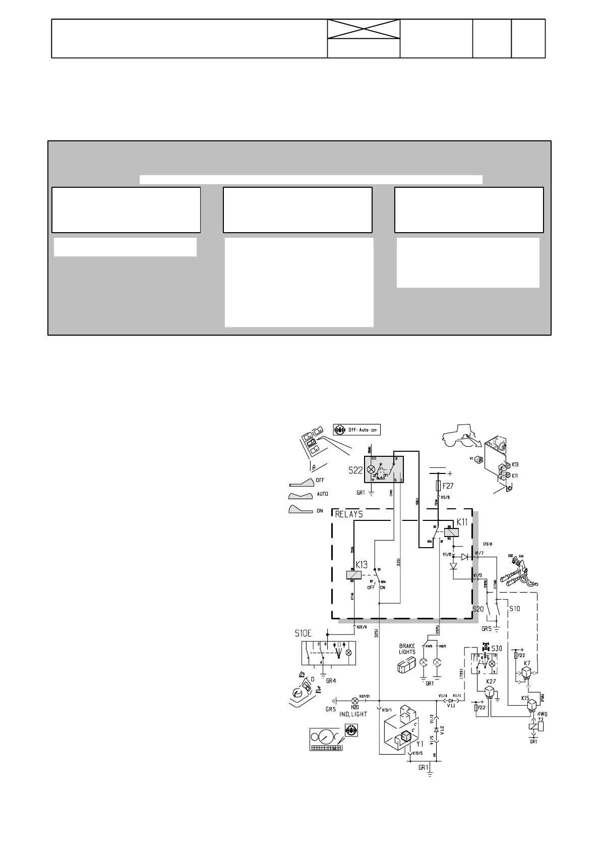
Picture 6. Diagram, differential lock, AC 2.3.
282
Model Code Page
31. Autocontrol 2.3
1. 8. 2000
6000--8750 314 10
The function of the differential lock has been changed in the latest tractors (AC 2.3):
(concerns also HiTech models 6250Hi ---8950Hi).
Note! Manufacturing of AC 2.3, K44242 ---. In connection with modification of the differential lock function, relay K12 has been
removed and diodes V3 are for solenoid valves. Wiring diagram on pages 310/83---88 incl. AC 2.3.
1. Control of differential lock
--- the lock is always engaged
except when brake pedal/pedals
are depressed or when the power
lift is in the transport position. The
lock engages when the brake
pedal/pedals are released or when
the lift/stop/lower switch is in the
lowering position or in the middle
position.
--- the differential lock is disenga-
ged.
--- the lock is always engaged
except when brake pedal/pedals
aredepressed.Thelockengages
when the brake pedal/pedals are
released.
The lock is controlled with a three ---position rocker switch on the driver’s right.
A. Rocker switch front edge
depressed.
B. Rocker switch in the mid-
dle position.
C. Rocker switch rear edge
depressed.
C. Differential lock control in AC 2.3
Depress the diff. lock rocker switch front edge. Now the
lock must be disengaged and the pilot light must not be on.
Solenoid valve Y1 must be unenergised.
This shows that:
--- rocker switc h front position is OK.
Press the rocker switch to the middle position, at which time
the lock must become engaged and the pilot light must
come on. Solenoid valve Y1 must be energised.
This shows that:
--- diff. lock pilot light and its wires a re OK.
--- rocker switch middle position is OK
While the rocker switch is in the middle position, depress
the brake pedal/pedals, at which time the lock must be di-
sengaged and the pilot light goes out. When the brake pe-
dalsarereleased,thelockmustbeengagedandthepilot
light comes on.
This shows that:
--- brake pedal switches S10 and S20 are OK
--- r e l a y K 1 1 i s O K
While the diff. lock rocker switch is in the middle position,
press the power lift “lower/stop/lift” switch S10E into the
transport position. Now the diff. lock must be disengaged.
Press the power lift switch back to the middle or lowering
position and the diff. lock must be engaged.
This shows that:
--- switch S10E is functioning properly
--- r e l a y K 1 3 i s O K
Depress the diff. lock rocker switch rear edge. In this positi-
onthelockmustbeonandalsothepilotlight.
This shows that:
--- diff. lock switch rear position is functioning properly.
While the rocker switch rear edge is down, depress the bra-
ke pedal/pedals, at which time the lock must be disenga-
ged. When the brake pedals are released, the diff. lock is
engaged and the pilot light comes on. The use of the power
lift switch S10E must not affect the function of the lock.
This shows that:
--- r e l a y K 1 1 i s O K
IMPORTANT! When the 4WD rocker switch is in the middle
position, the 4WD is engaged, when the differential lock is en-
gaged.