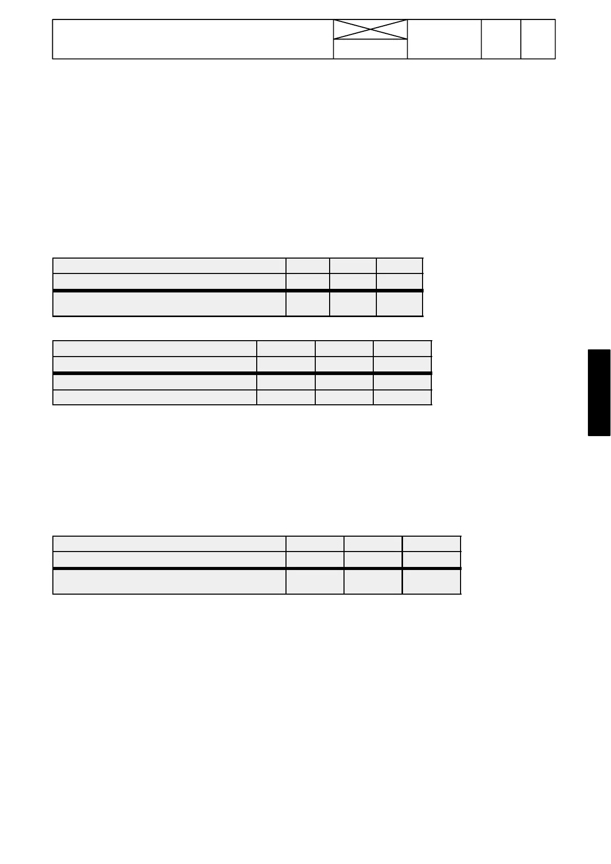
Important! If the tables below and the computer display
chart do not agree, check first that the cable between the
PC and the AC---IV unit is correctly connected to the PC
serial port and to the socket X10C.
The symbols after the names above the thick lines are
connector pins from which possible voltage measurements
canbedone.Thusthetablesbelowcanbeusedfor
trouble shooting even though You don’t have a PC.
429
Model Code Page
35. Autocontrol IV
1. 1. 1994
6600E
8100E-- 8750E
352 3
In the tables below the marks above the thick line and the
corresponding marks on the PC display should be similar with
the given switch and pedal positions under the thick line.
For these checks it is presumed that the tractor hydraulics
and mechanics are in perfect condition. During the test cur-
rent is switched on to the tractor but the engine is stopped (if
not otherwise informed)
A. Fault tracing, front wheel drive control
Input signals to ECS for controlling 4WD (DIGITAL INPUTS).
4WD A/M (A2C/14) 0 0 1
4WD MANUAL 1/0 (A2C/38) 0 1 0
A / M --- S W I T C H ( M
1=
rear edge down, M
2
=middle pos.
A=front edge down)
M
1
M
2
A
BRAKE LEFT (A2C/9) 0 1 0
BRAKE RIGHT (A2C/19) 0 0 1
LEFT BRAKE PEDAL U=Up D=Down U D U
RIGHT BRAKE PEDAL U=Up.D=Down. U U D
--- If the marks above the thick lines agree with the corresponding marks on the computer display, the input signals are OK. If not,
the fault lies in the switch in question or its wiring is faulty.
--- Input signals from the radar, front axle speed sensor and gearbox sensor are checked with a calibrating test, see page 351/2
or according to the instruction F on page 352/7.
Output signals from ECS for controlling 4WD (DIGITAL OUTPUTS)
4WD SOLENOID (A1C/38) 1 0 1
4WD LAMP (A1C/35) 0 1 0
A / M --- S W I T C H ( M
1=
rear edge down, M
2
=middle
position, A=front edge down.
M
1
M
2
A
--- If the marks above the thick line agree with the corresponding marks on the computer display, but the system does not function,
the possible fault lies in the solenoid valve, indicator light or their wirings are faulty.
--- If the output signals on the PC display differ from the marks in the table above, the ECS is faulty and should be changed.