451
Model Code Page
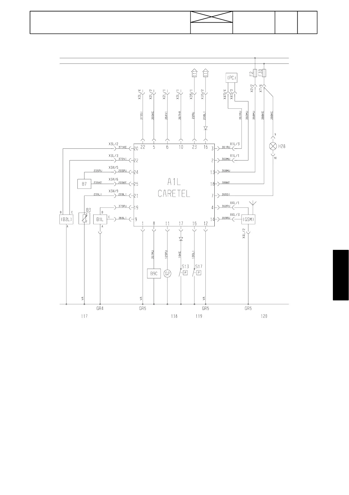
31. CareTel
1. 4. 1997
6000--8750 361 3
Wiring diagram (see also diagrams on pages 310/33---38)
Position of connectors:
X34: Connector in the rear part of the lever console (9 pins)
X35: Connector in the lever console (9 pins)
X43: Socket on the lever console on the driver’s right (8 pins)
X2: Connector in the fuse box (9 pins)
X7: Connector in the fuse box (9 pins)
X1L: Under the AC/ACD switch panel in the lever console on the driver’s right (8 pins)
X2L: In the steering wheel console under the dashboard (3 pins)
X3L: In the steering wheel console under the dashboard (9 pins)
X4L: InthecabroofontheLHside(3pins)
GR4: Earth point in the rear part of the lever console
GR5: Earth point on the cab front wall under the dashboard
Ru = brown
Pu = red
Ke = yellow
Si = blue
Mu = black
Vi = green
Va = white
Ha = grey
Li = lilac