491
Model Code Page
37. Autocontrol 5
1. 8. 2000
370 25
6250--8950
1. 10. 1999
1
2
3
4
5
6
7
8
9
10
1
2
3
4
5
6
7
8
9
10
11
12
13
14
1
2
3
4
5
6
7
8
9
10
11
12
13
14
1
2
3
4
5
6
7
8
9
10
11
12
13
14
1
2
3
4
5
6
1
2
3
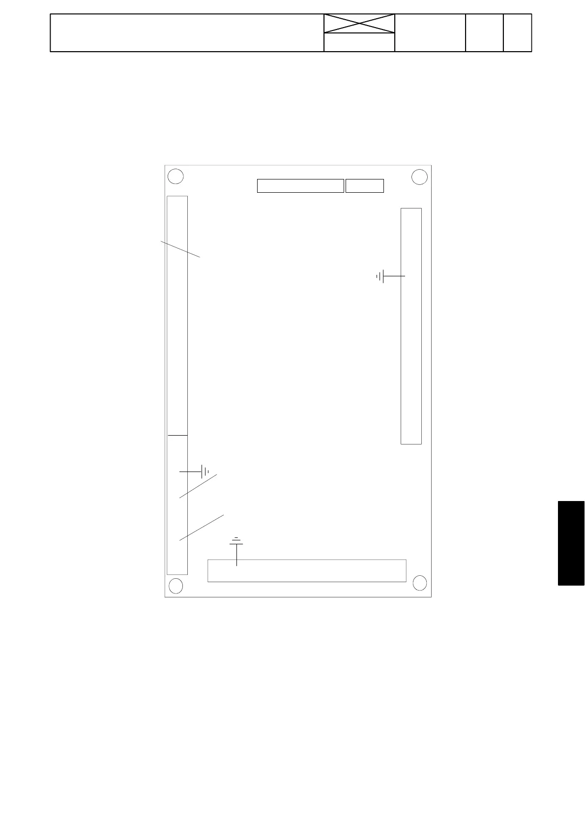
VALTRA
A C --- 5
Transmission control
Supply +12 V
GND
F6 PTO---speed (B7)
F5 Shuttle sign. (B13)
F4 Shuttle sign., (B12)
Reserve
F2 Gearbox speed, (B6)
F1 Engine speed, (B11)
DO 6 PTO pilot light
Out temp. A1 (B17)
Oil temp. A2 (B14)
Gas pedal supply A3 (B15)
Gas pedal sign A3 (B15)
GND A3 (B15)
Clutch pedal supply A4 (B16)
Clutch pedal sign. A4 (B16)
A4 GND (B16)
DPS up d01 (S23)
DPS down d02 (S23)
HiShift d03 (S45)
PTO start d04 (S25)
Driver detection d05 (S60)
Clutch pedal limit d06 (S9)
DPS auto1/auto 2 d07 (S47)
DPS auto/manual d08 (S47)
Direction F d09 (S40)
Direction R d10 (S41)
DPS pre---selection d11 (S51)
PTO speed 1 d12 (S28)
PTO speed 2 d13 (S29)
Seat direction d14 (S35)
PTO stand---by d15 (S25)
Hand brake d16 (S15)
P6 PTO---solenoid (Y2)
DO 5 Hand brake relay (---J38342, LCD display)
P5 R---solenoid (Y12
DO 4 LCD display
P4 F---solenoid (Y11)
DO 3 LCD display
P3 DPS---solenoid 3 (Y17)
DO 2 LCD display
P2 DPS --- so l e n o i d 2 ( Y 6)
DO 1 LCD display
P1 DPS---solenoid (Y4)
GND
GN D L C D --- d i s p l a y
R S --- 2 3 2 TX
RS---232 RX
RS---232 GND
*(CAN 1 HI)
*(CAN 1 LO)
*(CAN 1 GND)
*(CAN 2 HI)
*(CAN 2 LO)
*(CAN 2 GND)
A1A1
A1A2
A1A3
A1A4
A1A5
*) CAN 1 and CAN 2 data transfer
channels are not in use
d=digital input (on/off)
A=analog input (changing)
F=frequency input (speed)
Data transfer channels
DO=digital output
P6 to display
P=output to proportional valves
INPUT
OUTPUT
INPUT
+ 7 , 7 --- 8, 3 V
+ 7 , 7 --- 8, 3 V
GND, sensors
(only TwinTrac)
A. Connector pins of AC 5 control unit
6. Others
NOTE! Connectors of AC 5.2, see page 371/15.