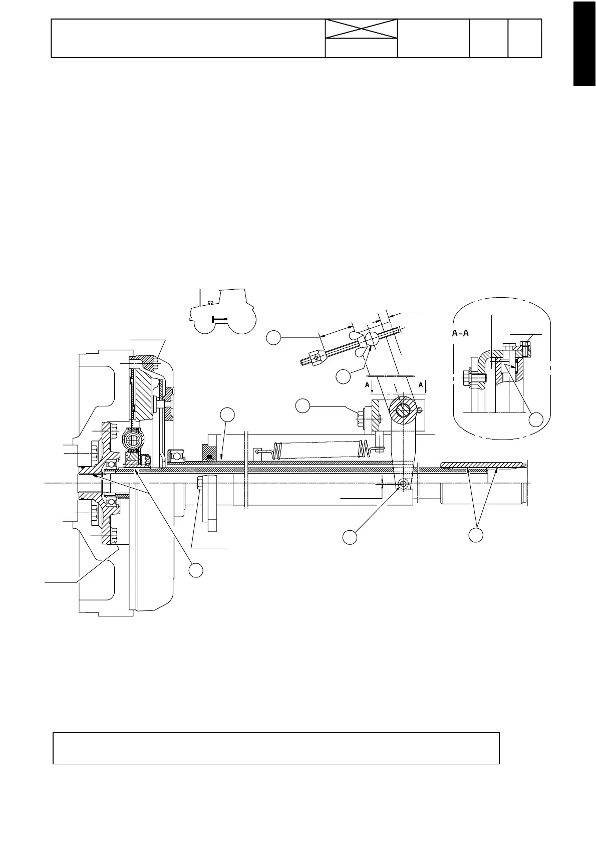
Figure 1. Clutch with release mechanism up to ser. no. 659477.
1. Universal grease
2. Pressure---resistant grease
3. Screw for adjusting position of release fork: 0,2 --- 0,3 mm below the centre line.
Thus the position of the release bearing is correct when the tube is in the front position
4. When changing the clutch disc the distance between the wing nut and adjuster stop is set to 50 mm.
NOTE! On HiTech tractors, which have a P owershift Shuttle , there is not a clutch assembly on the flywheel, but
only a drive disc, see page 410/4A.
635
Model Code Page
41. Clutch
1. 11. 1998
6000--8750 410 3
15. 5. 1993
Clutch, description
Important! Construction of clutch release mechansim from
ser. no. 659478,seepage410/8.
Models 6100---8100 are provided with a single dry---disc
clutch of the cup spring type. The clutch is operated mechan-
ically. The disc is provided with damping springs (not on Hi---
Trol models). Clutch disc diameter is 330 mm and it has or-
ganic linings (asbestos---free) (8400 has ceramic linings).
The clutch transmits power from the flywheel through a tubu-
lar shaft (clutch shaft) to the input shaft of the quick---shift gear
(or reverse shuttle), and further to the gearbox. The clutch
shaft front end is supported with a bearing. The clutch shaft
front end splines are engaged with the disc hub splines. The
clutc h shaft rear end is connect ed to the gearbox input shaft
with a coupling sleeve.
The release bearing is fitted at the end of a tube, the rear end
of which is controlled by the clutch lever. At the front end the
tube is supported in a guide sleeve
Pedal travel is adjusted by means of the wing nut on the link
rod. Disc wear is indicated by the distance between the wing
nut and the adjuster stop.
The pump drive shaft, which is driven by the drive flange on
the flywheel, runs inside the clutch shaft.
21---25 Nm
40---50 Nm
72---88 Nm
6 --- 6, 5 mm
50 mm
12,5 mm
21---25 Nm
0,2---0,3 mm
40---50 Nm
1
1
1
2
2
1
3
4